Recent progress of RF cavity study at Mucool Test Area
140 likes | 327 Vues
Recent progress of RF cavity study at Mucool Test Area. Katsuya Yonehara APC, Fermilab. Ionization cooling channel. Magnet. Magnet. RF cavity. Absorber. Beam envelop. Longitudinal momentum is regained by RF cavity. μ beam. RF cavity is embedded in strong B field (> 2 T).

Recent progress of RF cavity study at Mucool Test Area
E N D
Presentation Transcript
Recent progress of RF cavity study at Mucool Test Area Katsuya Yonehara APC, Fermilab
Ionization cooling channel Magnet Magnet RF cavity Absorber Beam envelop Longitudinal momentum is regained by RF cavity μ beam RF cavity is embedded in strong B field (> 2 T) After π → μ decay & μ collection Achievable smallest transverse beam phase space is determined by focus strength (β⊥) and Z & A of cooling absorber Perpendicular momentum after cooling absorber becomes smaller due to ionization energy loss process Perpendicular momentum before cooling absorber NuFact'11 - K. Yonehara
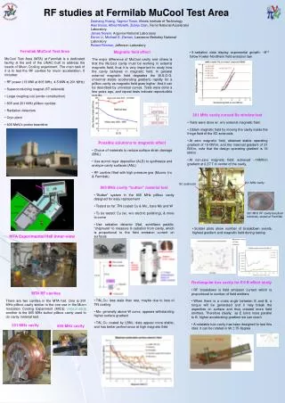
Problem: B field effect on RF cavity A. Bross, MC’11 Data were taken in an 805 MHz vacuum pillbox cavity Required E in cooling channel X Gradient in MV/m >2X Reduction @ required field Peak Magnetic Field in T at the Window NuFact'11 - K. Yonehara
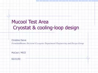
Mucool Test Area (MTA) & work space Multi task work space to study RF cavity under strong magnetic fields & by using intense H- beams from Linac MTA exp. hall Entrance of MTA exp. hall 200 MHz cavity Compressor + refrigerator room SC magnet 400 MeV H- beam transport line Workstation NuFact'11 - K. Yonehara
Illustrated “Standard model” of RF breakdown event RF cavity wall RF cavity wall 3. High energy e- smashes on cavity wall and generates secondary e- 1. An “asperity” emits a surface electron 2. Electron gains kinetic energy from E 4. Electron heats up cavity wall 5. Repeat heating and cooling wall material induces wall damage 6. Some amount of wall material is taken off from wall and generates dense plasma near surface Show just dominant process B field confines an electron beam and enhances breakdown process as shown in slide 3 NuFact'11 - K. Yonehara
Material search • High work function & low Z element can be a good material for cooling channel • Beryllium & Aluminum are good candidate M. Zisman, Nufact’10 Simulated max grad in an 805 MHz RF cavity with Be, Al, and Cu electrodes Beryllium button assembled 805 MHz pillbox cavity Test will be happened in this summer & fall NuFact'11 - K. Yonehara
Special surface treatment • By treating cavity surface by using superconducting cavity technique a field enhancement factor significantly goes down • In addition, we propose a very thin coat on the cavity wall by using Atomic Layer Deposition (ALD) method to reduce a field enhancement factor • Or, apply E × B force on the wall surface to defocus dark current • Test has been done • Investigation & analysis are on going NuFact'11 - K. Yonehara
RF R&D – 201 MHz Cavity TestTreating NCRF cavities with SCRF processes A. Bross, MC’11 • The 201 MHz Cavity – 21 MV/mGradient Achieved (Design – 16MV/m) • Treated at TNJLAB with SCRF processes – Did Not Condition • But exhibited Gradient fall-off with applied B 1.4m NuFact'11 - K. Yonehara
Fill up dense gas to slow down dark current 805 MHz High Pressure RF (HPRF) cavity has been successfully operated in strong magnetic fields Maximum electric field in HPRF cavity Schematic view of HPRF cavity • Gas breakdown: • Linear dependence • Governed by electron mean free path • Metallic breakdown: • (Almost) constant • Depend on electrode material • No detail study have been made yet Metallic breakdown Operation range (10 to 30 MV/m) Gas breakdown P. Hanlet et al., Proceedings of EPAC’06, TUPCH147 NuFact'11 - K. Yonehara
Study interaction of intense beam with dense H2 in high gradient RF field ν= 802 MHz Gas pressure = 950 psi Beam intensity = 2 108 /bunch RF power is lost when beam is on RF power is recovered when beam is off Ionization process RF pulse length (80 μs) p + H2 → p + H2+ + e- Beam signal (x8) (8 μs) 1,800 e- are generated by incident p @ K = 400 MeV Does intense beam induce an electric breakdown? → No! RF power reduction due to beam By comparing RF power reduction and light intensity in beam induced plasma with these at real RF breakdown, beam induced plasma density must be very thin. RF power reduction due to RF breakdown Beam induced light • Observed plasma density in RF breakdown • = 1019 cm-3 • Estimated beam induced plasma density • = 1014 cm-3 RF breakdown light NuFact'11 - K. Yonehara
Preliminary estimation of plasma loading effect in HPRF cavity for cooling channel From RF amplitude reduction rate, RF power consumption by plasma can be estimated ν= 802 MHz Gas pressure = 950 psi Beam intensity = 2 108 /bunch Joule @ E = 20 MV/m electrons@ t = 200 ns Hence, energy consumption by one electron is (including with initial beam intensity change) Joule Muon collider: ne per one bunch train = 1013μ × 103e = 1016 electrons → 0.6 Joule Neutrino Factory: ne per one bunch train = 1012μ × 103e = 1015 electrons → 0.06 Joule • A 201 MHz pillbox cavity stores 8.5 Joule of RF power • > For MC, 0.6/8.5 of RF power reduction corresponds to 4 % of RF voltage reduction • > For NF, 0.06/8.5 of RF power reduction is negligible • Plasma loading effect in higher frequency pillbox RF cavity will be severe since the • cavity stores less RF power • > Need some technique to reduce plasma loading effect NuFact'11 - K. Yonehara
Improve performance of HPRF cavity Doping electronegative gas (SF6, NH3) Induce plasma instability by E × B force Local electric field due to plasma oscillation Apply B⊥E to induce E×B force (ex. Lifetime of wakefield plasma is O(fs)) This test will be done soon. • Other possible improvement: • Large charge capacitive RF cavity • Plasma loaded RF cavity has a big impedance change • > Modify Klystron (ex. multiple RF power injection) to match the impedance • Plasma loading in denser gas tends to be smaller • > Simply fill denser gas in the cavity to reduce plasma loading effect NuFact'11 - K. Yonehara
Summary • MTA is a multi task working space to investigate RF cavities for R&D of muon beam cooling channel • Intense 400 MeV H- beam • Handle hydrogen (flammable) gas • 5 Tesla SC solenoid magnet • He cryogenic/recycling system • Pillbox cavity has been refurbished to search better RF material • Beryllium button test will be happened soon • E × B effect has been tested in a box cavity • Under study (result seems not to be desirable) • 201 MHz RF cavity with SRF cavity treatment has been tested at low magnetic field • Observed some B field effect on maximum field gradient • Further study is needed (large bore SC magnet will be delivered end of 2011) • HPRF cavity beam test has started • No RF breakdown observed • Design a new HPRF cavity to investigate more plasma loading effect NuFact'11 - K. Yonehara
Additional comments/corrections from my presentation • Slide 11: There were assumptions to estimate power deposition in an electron swarm • Use the same cavity length as an 805 MHz HPRF test cavity: 0.0177 m • Electron production ratio (103 electrons/muon) is estimated from 950 psi H2 gas @ room temperature • For NF, this number will be fine • For MC, we will put 2940 psi @ room temperature • Then, the number of electrons in the cavity will be 3 103 electrons/muon • E field drops 89 % • E amplitude reduction can be managed by tuning RF frequency • We do not use crest for cooling channel • Acceleration field can be tuned by adjusting RF frequency (ex. 200.000 MHz → 199.679 MHz for 60 ns muon beam pulse length) NuFact'11 - K. Yonehara