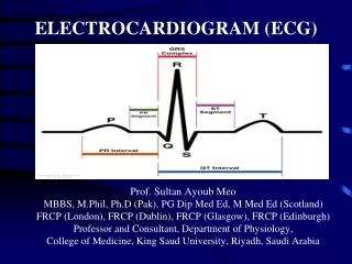
The Normal Electrocardiogram
The Normal Electrocardiogram. The Basic Rule:. The basic rule of electrocardiography states that:

The Normal Electrocardiogram
E N D
Presentation Transcript
The Basic Rule: • The basic rule of electrocardiography states that: • If the flow of electric current is TOWARDS a positive electrode, the wave forms produced will be positive (above the isoelectric line), and if the flow of electric current is directed AWAY from a positive electrode, the wave forms will be negative (below the isoelectric line)
Characteristics of the normal ECG • P wave is caused by electrical potentials generated when the atria depolarize before atrial contraction begins • QRS complex is caused by potentials generated when the ventricles depolarize before contraction • Both P and QRS complex are depolarization waves • T wave is caused by potentials as the ventricles recover from the state of depolarization. This process normally occurs in ventricular muscle 0.25 to 0.35 second after depolarization. • T wave is also known as repolarization wave
ECG Recording • No potential is recorded in the ECG when the ventricular muscle is either completely polarized or completely depolarized • Only when the muscle is partly depolarized does current flow from one part of the ventricles to another part • Therefore, current also flows to the surface of the body to produce the electrocardiogram
Atrial and Ventricular Contraction and Waves of ECG • Before contraction of muscle can occur, depolarization must spread through the muscle to initiate the chemical processes of contraction • Ventricles remain contracted until after repolarization has occurred (i.e. until after the end of T wave) • The atria repolarize about 0.15 to 0.20 sec after termination of P wave • This coincides with the QRS complex • Therefore, atrial repolarization (atrial T wave) is obscured by the QRS complex
Ventricular T Wave • Ventricular muscle begins to repolarize about 0.25 to 0.35 sec after the beginning of depolarization wave (the QRS complex) • T wave is a prolonged wave • Its voltage is considerably less than the voltage of the QRS complex • Partly because of its prolonged length
approx. 0.44 s 0.12-0.2 s QT PR R T Atrial muscle depolarization P Q S Ventricular muscle repolarization Ventricular muscle depolarization The Normal ECG Right Arm “Lead II” Left Leg
Normal Voltages in the ECG • When ECG is recorded from electrodes on the two arms or on one arm and one leg, the voltage of the QRS complex is usually 1.0 to 1.5 mV from the top of the R wave to the bottom of the S wave • The voltage of P wave is between 0.1 and 0.3 mV • And that of T wave is between 0.2 and 0.3 mV
P-Q or P-R Interval • The time between beginning of P wave and the beginning of QRS complex is the interval between electrical excitation of atria and ventricles. • It is called P-Q interval • It is about 0.16 second • P-Q interval is also called P-R interval (since Q wave is sometimes absent)
Q-T Interval • Q-T interval: Contraction of the ventricles lasts almost from the beginning of the Q wave to the end of T wave • Q-T interval is about 0.35 second
Rate of Heartbeat as determined from ECG • The normal interval between two successive QRS complexes in the adult person is about 0.83 second. • This is a heartrate of 60/0.83 times per minute, or 72 beats per minute.
Methods for Recording ECG • Pen Recorder • Electronic Recorders
Recording electrical potentials from a partially depolarized mass of syncytial cardiac muscle
Flow of Electrical Currents in the Chest Around the Heart • The heart is suspended in a conductive system • When one portion of the ventricles depolarizes and therefore becomes electronegative with respect to the remainder, electrical current flows from the depolarized area to the polarized area • Average current flow occurs with negativity toward the base of the heart and with positivity toward the apex
Flow of Electrical Currents in the Chest Around the Heart • Depolarization spreads from endocardium toward outward through the ventricular muscle mass
Main Cardiac Vector RA LA Main Cardiac Vector LL
Lead Systems: • In 1902, Willem Einthoven recorded the first ECG. He determined that the heart lies at the center of the electrical field determined by the axis of three standard “Limb” electrodes. • Different “leads” or views of the electrical patterns produced were obtained by electrodes placed on the Left Arm, Right Arm, and Left Leg.
Three Bipolar Limb Leads • Bipolar recordings vs Unipolar recordings: Total 12 leads • Standard Bipolar Limb Leads: • Lead I: Negative terminal of the ECG is connected to the right arm and positive terminal to the left arm • Lead II: Negative terminal is connected to the right arm and positive terminal to the left leg • Lead III: Negative terminal of the ECG is connected to the left arm and the positive terminal to the left leg
ECG • Einthoven’s Law: if the electrical potentials of any two of the three bipolar limb electrocardiographical leads are known at any given instant, the third one can be determined mathematically by simply summing the first two. • Einthoven’s triangle • Lead I: 0.5 mV • Lead III: 0.7 mV • Lead II: 1.2 mV
Six Standard Chest (Precordial) Leads • Often ECG is recorded with one electrode placed on the anterior surface of the chest directly over the heart • This electrode is connected to the positive terminal of ECG • Usually six standard chest leads are recorded, one at a time, from the anterior chest wall. • V1, V2, V3, V4, V5 and V6 • Because the heart surfaces are close to the chest wall, each chest lead records mainly electrical potential of the cardiac musculature immediately beneath the electrode
Placement of Chest Leads The “Precordial Leads” 4th intercostal space V1 V2 Each of the precordial leads is unipolar (1 electrode constitutes a lead) and is designed to view the electrical activity of the heart in the horizontal or transverseplane V3 V6 V5 V4 V1 - 4th intercostal space - right margin of sternum V2 - 4th intercostal space - left margin of sternum V3 - linear midpoint between V2 and V4 V4 - 5th intercostal space at the mid clavicular line V5 - horizontally adjacent to V4 at anterior axillary line V6 - horizontally adjacent to V5 at mid-axillary line
Six Standard Chest Leads • In leads V1 and V2, the QRS recordings of the normal heart are mainly negative because the chest electrode in these leads is nearer to the base of the heart than to the apex • The base of the heart is the direction of electronegativity during most of the ventricular depolarization process. • Conversely, QRS complexes in leads V4, V5 and V6 are mainly positive because the chest electrode in these leads is nearer the heart apex, which is the direction of electropositivity during most of depolarization.
Augmented Unipolar Limb Leads • Augmented or vector leads produce a small electrical potential, which needs to be augmented/magnified. • AVR: LA+LL (negative), RA (positive) • AVL: RA+LL (negative), LA (positive) • AVF: RA+LA (negative), LL (positive)
Augmented Unipolar Limb Leads Augmented Voltage Leads AVR, AVL, and AVF RA & LA - LEAD AVR LEAD AVL RA LA + + By combining certain limb leads into a central terminal, which serves as the negative electrode, other leads could be formed to "fill in the gaps" in terms of the angles of directional recording. These leads required augmentation of voltage to be read and are thus labeled. - - LL & LA RA & RL + LL LEAD AVF