Electron Charge-to-Mass Ratio Experiment: Design & Analysis
This experiment aims to determine the charge-to-mass ratio of an electron by designing and conducting your own procedures. Learn how to analyze data, account for uncertainties, and write a scientific report following Hendrik Lorentz's magnetic force principles. You will explore the interaction of electric and magnetic fields, electron acceleration, and energy conservation in the experimental setup. Gain hands-on experience in physics lab practices and data interpretation.

Electron Charge-to-Mass Ratio Experiment: Design & Analysis
E N D
Presentation Transcript
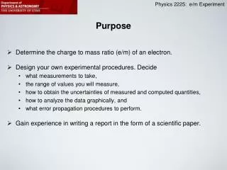
Purpose • Determine the charge to mass ratio (e/m) of an electron. • Design your own experimental procedures. Decide • what measurements to take, • the range of values you will measure, • how to obtain the uncertainties of measured and computed quantities, • how to analyze the data graphically, and • what error propagation procedures to perform. • Gain experience in writing a report in the form of a scientific paper.
Background 1892: Hendrik Lorentz introduces the force acting on a charged particle moving through a magnetic field (the Lorentz force, or magnetic force): • The cross product means: • Only the components of the vectors v and B that are perpendicular to each other contribute to the force. • The force is perpendicular to both the vector v and the vector B.
(points into the page) q The charge here is assumed to be positive. For negative charges the force would be downwards.
circular path r q (points into the page) q • The force continually changes the direction of the velocity, but not it’s magnitude. • The direction of the force changes also and it’s magnitude also remains the same.
For Circular Motion (Radius r) Derive expression for e/m(v,B,r)=…..
Getting the electron up to speed …and knowing what that speed is. Speed increases as electrons approach plate Some electrons miss the plate and fly through the hole in the plate. electron beam comes out of hole. filament electrons v v v E Ifilament Many electrons return because they hit the plate. (Note: return path of electrons is opposite to conventional current.) filament Voltage (6V) accelerating voltage (150V-300V) The filament current heats up the filament electrons get enough energy to exit the filament. Electrons get accelerated by the force in the electric field (created by the accelerating voltage).
Getting the electron up to speed …and knowing what that speed is. electron has potential energy = eVacc and kinetic energy = 0 electron has potential energy = 0 and kinetic energy = ½ mv2 v v v Conservation of energy:
Generating the Magnetic Field A pair of Helmholtz coils a B I I I Magnetic field in the center of the Helmholtz coil pair. I N turns of wire in each coil.
Power Supplies • Before you switch on the power supply: • Identify all components according and verify that all connections are as • shown in the lab manual. • Identify on the high voltage power supply the dial that controls the • accelerating voltage: Turn that dial all the way counterclockwise into the • zero position. • Identifyon the low voltage power supply the two dials that control the • current through the Helmholtz coil: Turn both dials (voltage control and • current control) counterclockwise into the zero position. • Identify on the low voltage power supply the heater voltage dial. This is a • step dial. Verify that it is set to 6 Volts.
High Voltage Supplies Older model Newer model
Low Voltage Power Supplies Older model Heater voltage: must be dialed to 6V Newer model Helmholtz coil current and voltage regulation
Switching on the Power Supplies • Now switch on both power supplies. Check and make sure that the Helmholtz coil current is zero and the accelerating voltage is also zero. • Look at the tube: You should see the filament glow orange/yellow. • Carefully dial up the accelerating voltage on the high voltage power supply to about 200V (never exceed 300V). • Regulating the current in the Helmholtz coil: • There are 3 knobs that control voltage and current through the Helmholtz coil: • Current adjustment knob for Helmholtz coils on the e/m apparatus. • Current adjustment knob on low voltage power supply. • Voltage adjustment knob on low voltage power supply. • Next page: how to use these three knobs.
Regulating the Current in the Helmholtz Coil: First turn DC VOLTAGEADJUST to zero (all the way counterclockwise) Then turn DC CURRENT ADJUST all the way clockwise (max. current). Then turn current adjust knob On the e/m apparatus all the way clockwise (max. current). The current meter should STILL READ ZERO.
Regulating the Current in the Helmholtz Coil: Carefully turn DC VOLTAGE ADJUST clockwise. Watch the current meter! When current meter reaches 2 Amps: Stop!! Leave at this setting!! From now on only regulate the current with this knob on the e/m apparatus Totally clockwise = 2A Totally counterclockwise = 0A
Switching Off Power Supplies • Before you switch off the power supply: • Identify on the high voltage power supply the dial that controls the • accelerating voltage: Turn that dial all the way counterclockwise into the zero position. • Identifyon the low voltage power supply the two dials that control the current through the Helmholtz coil: Turn both dials (voltage control and current control) counterclockwise into the zero position. • Now switch off.
Hints When measuring the radius of the electron’s circular path, take advantage of the mirror-scale behind the tube: - Move your head to the left or right until the mirror image of the beam overlaps the actual electron beam. Then read off the scale. - Repeat the procedure for the left side. - Determine diameter from the two values (radius is half of that). Read off left side Read off right side
Important for the Longevity of Apparatus • Never exceed 300V on the accelerating voltage. Always monitor this voltage on the attached volt meter when changing that voltage. • Never exceed 2A on the Helmholtz coil current. Always monitor this current with the attached current meter when changing that current. • Always dial down accelerating voltage and Helmholtz current to zero before switching off the power supplies.
Lab Report • Lab report must be written in the form of a scientific paper • (see example in the back of the lab manual). • Each person must write their own lab report • (no group report for this experiment). • You have 1 week to complete and submit the lab report. • Late lab reports will get a deduction of 5% per day late • (e.g., if your report is 3 days late you will only get credit for 85% of the score that you would have gotten if you submitted on time).