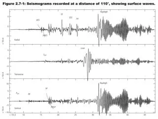
Surface Wave Propagation Preliminary work developing a method for surface wave detection
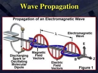
Surface Wave Propagation Preliminary work developing a method for surface wave detection. Amy Zheng. Ultrahigh Energy Neutrino Detection. UHE neutrinos will emit coherent radio frequency radiation that create the Askaryan effect [1].

Surface Wave Propagation Preliminary work developing a method for surface wave detection
E N D
Presentation Transcript
Surface Wave Propagation Preliminary work developing a method for surface wave detection Amy Zheng
Ultrahigh Energy Neutrino Detection • UHE neutrinos will emit coherent radio frequency radiation that create the Askaryan effect[1] • Signal strength is reduced due to ice’s absorption of bulk waves[2]
Surface Waves as a Detection Tool • In tandem with existing experiments ARA[4], ARIANNA[5], and ANITA[6] ARIANNA ANITA ARA
Surface Waves as a Detection Tool • Radiation from Askaryan cascade trapped in dielectric-dielectric layer between ice and air[3]
Why Use Surface Waves? • ~800 times more efficient than bulk waves[7] • Amplitudes fall at the rate • Attenuation length times > bulk waves • Claimed by ARIANNA[6] • If detection is viable, expanding existing experiments would be far less expensive • No drilling
Experimental Signatures • JPR claims • Signal strength for surface propagation > bulk propagation
Procedure • 1 sending + 2 receiving antennas • Oscilloscope displayed waveshape • Physically moved antennas and recorded phase distance • n calculated from λ • Not pure far-field
Example Antenna Placements • “Air” • “Surface” • “In”
Translating to refractive index Definition of Refractive Index
Sand 1000MHz Sand Bulk n=1.73
Half orientation • Contains constructive and destructive interference • Other antenna positions show higher attenuation
Measurement Complications • Imprecise measurements due to hand & eye observation • Sand tended to collect in the connectors • Angular error from planar disparity • Background EM noise & reflections often interfered
Future Steps • Experiment using ice as a medium • Increase antenna size (requires larger volume) • Amplify signal for far field measurements • Perform experiments in the Hutchinson salt mine (Dec. 2012) • Verify • Coax Zenneck waves
Acknowledgments • Dr. Besson • Marie Piasecki • Jordan Hanson • Andrew Johnannsen
References [1]G.A. Askaryan, Sov. Phys. JETP 14, 441 (1961) [2]Physics of Ice Core Records: 185-212 (2005) [3]J.P. Ralston, Phys. Rev. D 71, 011503 (2005) [4]For information on ARA, see http://ara.physics.wisc.edu/ [5]For information on ARIANNA, see http://arianna.ps.uci.edu/ [6]For information on ANITA, see http://www.phys.hawaii.edu/anita/. [7]Jordan Hanson, “Developing the Next Generation of UHE Neutrino Detectors in Antarctica” I. H. Malitson. Interspecimen Comparison of the Refractive Index of Fused Silica, J. Opt. Soc. Am. 55, 1205-1208 (1965) doi:10.1364/JOSA.55.001205 Colloquium Notes from John P. Ralston