Download
1 / 57
570 likes | 602 Vues
Dive into Chapter 2 to learn about signals, amplitudes, frequencies, data rates, and media types guiding data transmission in communication networks. Discussions include attenuation, distortion, noise, and mitigation techniques.

E N D
The Physical Layer Read Chapter 2
Putting the bits on the wire… Chapter 2
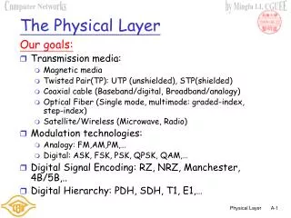
Terminology (1) • Transmitter • Receiver • Medium • Guided medium • e.g. twisted pair, optical fiber • Unguided medium • e.g. air, water, vacuum Chapter 2
Terminology (2) • Point-to-point • Direct link • Only 2 devices share link • Multi-point • More than two devices share the link Chapter 2
Terminology (3) • Simplex • One direction • e.g. Television • Half duplex • Either direction, but only one way at a time • e.g. police radio • Full duplex • Both directions at the same time • e.g. telephone Chapter 2
Continuous Signals Continuous signal:Intensity Varies in a smooth way over time, no breaks... Chapter 2
Discrete Signals • Discrete signal:Maintains a constant level then changes to another constant level Chapter 2
Periodic Signals • Periodic signal: The same pattern is repeated over time... Chapter 2
Amplitude, Frequency and Period... • Amplitude (A) • maximum strength of signal…Volts • Frequency (f) • Rate of change of signal, Hertz (Hz) or cycles per second • The period • Period = time for one repetition (T) • T = 1/f • Phase () • Relative position in time Chapter 2
Amplitude, Frequency and Period... Chapter 2
Wavelength () • :Distance occupied by one cycle. It is also the distance between two points of corresponding phase in two consecutive cycles • In a vacuum space: • c = 3*108 ms(speed of light in free space) • = cT • f = c Chapter 2
Baud • Definition: the unit baud measures the number of changes per second in the signal. • OR, how many times the signal changes its amplitude per second... Chapter 2
Spectrum & Bandwidth • Spectrum • range of frequencies contained in signal • Absolute bandwidth • width of spectrum • Effective bandwidth • Often just bandwidth • Narrow band of frequencies containing most of the energy Chapter 2
Data Rate and Bandwidth • Any transmission system has a limited band of frequencies • This limits the data rate that can be carried Chapter 2
The Maximum data rate of a channel • Nyquist: maximum data rate = 2 H log2 V bits/s • Shannon (Nyquist is an optimist) maximum data rate = H log2 (1+S/N) S/N….. Chapter 2
Analog and Digital Data Transmission • Data • Entities that convey meaning • Signals • Electric or electromagnetic representations of data • Transmission • Communication of data by propagation and processing of signals Chapter 2
Data • Analog • Continuous values within some interval • e.g. sound, video • Digital • Discrete values • e.g. text, integers Chapter 2
Signals • Means by which data are propagated • Analog • Continuously variable • Various media: wire, fiber optic, space • Speech bandwidth 100Hz to 7kHz • Telephone bandwidth 300Hz to 3400Hz • Video bandwidth 4MHz • Digital • Use only two levels of voltage Chapter 2
Data and Signals • Usually use digital signals for digital data and analog signals for analog data • Can use analog signal to carry digital data • Modem • Can use digital signal to carry analog data • Compact Disc audio Chapter 2
Transmission Impairments • Signal received may differ from signal transmitted • Analog - degradation of signal quality • Digital - bit errors • Caused by: • Attenuation • Distortion • Noise Chapter 2
Attenuation • Signal strength falls off with distance • Loss of energy due to the propagation of bits in long distance… • Depends on medium • Received signal strength: • must be enough to be detected • must be sufficiently higher than noise to be received without error Chapter 2
Distortion • Only in guided media • Propagation velocity varies with frequency • Bits do not arrive in the initial order... Chapter 2
Noise • Additional signals inserted between transmitter and receiver • Thermal: due to thermal agitation of electrons • Crosstalk: a signal from one line is picked up by another • Impulse: high amplitude Chapter 2
What To Do Against Attenuation, Distortion and Noise? • A media adapted to the distance/bit rate • Encoding schemes (we will see it later) Chapter 2
Media for Networks • Twisted pair • 2 twisted insulated copper wires • Twesting waires reduces interferences • Ex.: the telephone system • Category 3: Some megabits per sec. (for only few Kms, may need repeaters for longer distances) • Category 5: more twists per centimeter, less crosstalk, longer distance,more suitable for high speed computer communications… Chapter 2
Media for Networks • Coaxial cable • See fig. 2-3 on page 84 • Has a better shielding so it can span longer distance… • Higher speed… • Good noise immunity… • Baseband: 2Gbps for 1km, less speed for more kms (amplifiers are requiered), used in both voice and data transmission… • Broadband: oriented cable TV, mainly analog transmission, accuracy is not required, long distance… Chapter 2
Media for Networks • Fiber optics • See page 87 for an introduction to optical transmission system… • 3 main elements: the light source, the transmission medium and the light detector • A pulse of light=1 bit, absence=0bit • The transmission media is an ultra-thin fiber of glass • How to transmit… • Several Gbps for 30kms, 1 repeater per 30kms… Chapter 2
Future is With Fiber • Bigger bandwidths • Attenuation/distance is lower than copper • Not sensitive to electromagnetic interference • Lighter and thinner than copper • Difficult to tap Chapter 2
Wireless Links: The spectrum of telecommunication 1014 100 104 108 1012 1016 1022 Infrared UV Gamma X-Ray Radio Microwa. 104 105 106 107 108 109 1010 1011 1012 1013 1014 1015 1016 F(Hz) Fiber Satellite Twisted pair Coax Microwave Maritime FM Radio AM Radio TV Band LF MF HF UHF VHF Chapter 2
Different Bands of the Spectrum • Radio Transmission • Microwave Transmission • Infrared and Millimeter Waves • Lightwave Transmission Chapter 2
Relation Spectrum, Frequency, Data rate... • The frequency band is derived from l.f = c • Deriving gives the frequency band corresponding to a wavelength and wavelength interval is then :… Chapter 2
The Spectrum: A cake to Share • WARC (International) • FCC ( U.S. agency) Chapter 2
Radio Transmission • Easy to generate • Travel long distance, penetrate buildings • Omnidirectional • Properties depend on frequency • low frequencies, penetrates buildings well but sensitive to distance (1/r3). • High frequencies, travel in straight lines, absorbed by rain • Sensitive to interferences Chapter 2
Microwave Transmission • Travel long distance, (Does not penetrate buildings) • Not Omnidirectional. Travel in straight lines (transmitter and receiver must be carefully aligned) • Absorbed by rain • ISM band Chapter 2
Infrared and Millimiter Waves • Do not go thru solid walls • Good for indoor wireless LANs Chapter 2
Using the Telephone System for Computer Networks • Why? • What is the telephone system? • How does it work? • How can computers use it for communicating? Chapter 2
The Telephone System Toll office (We may have other levels of hierarchy…) Phone Local Loop End office Chapter 2
The Telephone System • Local loop • analog • twisted pair • one per user • Low bandwidth • Inter switches trunks • Use to be analog but is now digital (see page 109) • fiber • High bandwidth • Shared Chapter 2
Local loop for a Computer End office Local loop Analog Computer Modem Short digital connection RS 232 Codec Digital Chapter 2
Transmission impairments (Local Loop) • Attenuation • Delay distorsion • Noise Chapter 2
Modulation • Amplitude modulation • Frequency modulation (FSK) • Phase modulation (PSK) • Constellation patterns (see ex. in page 111) Chapter 2
Full/Half duplex • Other problems with telephone lines: • Echo effects: a person hears its own words after a short delay… • Echo suppressors: a device that detects human voice from one end and suppresses signals from the other end… switching… half duplex connection… • Echo cancelers… Estimates the echo and subtracts it from the original signal…Full duplex connection Chapter 2
InterfaceComputer (DTE)-Modem (DCE) • The RS 232 is a good example of physical layer protocol Protective ground (1) Transmit (2) Receive(3) Data Terminal Equipment Request To Send (4) Data Circuit-Term. Equipment Clear To Send(5) Data Set Ready(6) Carrier Detect(8) Data terminal Ready(20) Common Ground (7) Chapter 2
Interface Computer (DTE)-Computer (DTE) • With a null modem device we can use RS 232 to connect 2 DTE… Shield (1) DTE DTE Transmit (2) Receive(3) Request To Send (4) Clear To Send(5) Data Set Ready(6) Carrier Detect(8) Data terminal Ready(20) Common Ground (7) Chapter 2
Review End office Local loop Analog Digital RS 232 Computer Modem Digital Codec We looked in detail into this We focus now on trunks Chapter 2
Trunks: transporting many conversations on the same “wire” • Frequency Division Multiplexing • Wavelength Division Multiplexing (Fiber) • Time Division Multiplexing Chapter 2
Frequency Division Multiplexing • Let the signals we need to transmit working in D frequency. • All signals are raised in frequency by n.D’ such that D’ > D. The extra is called guard band. • All signals are added Chapter 2
Frequency Division Multiplexing(Example) • The phone voice is limited to D=3000 Hz frequency. • All signals are raised in frequency by n.D’ with D’=4000 Hz (two 500Hz guard band) • All signals are added Chapter 2
Frequency Division Multiplexing 4000Hz 1 group (60 to 108KHz) 12 1 super group 5 1 mastergroup 5 Chapter 2
Time Division Multiplexing • Works only for digital signals • Allocate time slots to every signal • Each signal has the exclusive use of the line for a given time slot Chapter 2