Download
1 / 34
420 likes | 838 Vues
WCDMA Air Interface Training Part 5 WCDMA Acquisition, Synchronization, and Handover. WCDMA Physical Layer Procedures. Physical Layer Timing and procedures BS Downlink timing Fast Synchronization Codes Synchronization Code 1 (PSC) Synchronization Code 2 (SSC i ) Downlink Scrambling Codes

E N D
WCDMA Air Interface TrainingPart 5 WCDMA Acquisition,Synchronization,and Handover
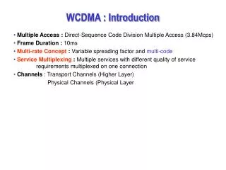
WCDMA Physical Layer Procedures • Physical Layer Timing and procedures • BS Downlink timing • Fast Synchronization Codes • Synchronization Code 1 (PSC) • Synchronization Code 2 (SSCi) • Downlink Scrambling Codes • Used by UE to distinguish desired Base Station • 8192 possible codes, 64 Scrambling Code Groups • Slot Synchronization • Frame Synchronization • System Timing Synchronization • Soft Handover • Random Access protocol • Packet Access protocol • Inter-Frequency Handover
#0 #1 #2 #3 #4 #5 #6 #7 #8 #9 #10 #11 #12 #13 #14 AICH access slots Downlink Transmission Timing 3GPP TS 25.211 ¶ 7.0 10 ms Frame SCH (PSC+SSC)P-CCPCHS-CCPCHPICHAICHPDSCHDPCH Primary SCH Secondary SCH Common PilotChannel CPICH (Common Pilot Channel) P-CCPCH, (SFN modulo 2 = 1) P-CCPCH, (SFN modulo 2 = 0) Primary CCPCH(Broadcast Data) t S-CCPCH,k k:th S-CCPCH Secondary CCPCH(Paging, Signaling) t PICH PICH for n:th S-CCPCH Paging Indication Channel t DPCH,n Dedicated PhysicalControl/Data Channel n:th DPCCH/DCDPH Any PDSCH Downlink Shared Channel t S-CCPCH,k = N x 256 chips t DPCH,n = N x 256 chips t PICH = 7680 chips (3 slots)
Downlink Scrambling Codes 3GPP TS 25.213 ¶ 5.2.2 • Downlink Scrambling Codes • Used to distinguish Base Station transmissions on Downlink • Each Cell is assigned one and only one Primary Scrambling Code • The Cell always uses the assigned Primary Scrambling Code for the Primary and Secondary CCPCH’s • Secondary Scrambling Codes may be used over part of a cell, or for other data channels 8192 Downlink Scrambling CodesEach code is 38,400 chips of a 218 - 1 (262,143 chip) Gold Sequence Code Group #1 Code Group #64 Primary SC0 Primary SC7 Primary SC511 Primary SC504 Secondary Scrambling Codes (15) Secondary Scrambling Codes (15) Secondary Scrambling Codes (15) Secondary Scrambling Codes (15)
X 17 16 14 13 12 11 10 9 8 7 6 5 4 3 2 1 0 15 I Q Y 17 16 15 14 13 12 11 10 9 8 7 6 5 4 3 2 1 0 Downlink Scrambling Codes 3GPP TS 25.213 ¶ 5.2.2 • Downlink Scrambling Code Generation 10 mSec Gold Code formed by Modulo-2 Addition of 38,400 chips from two m-sequences Primary Scrambling code i (where i = 0,...,511) is generatedby offsetting the X sequence by (16*i) clock cycles from the Y sequence Initial Conditions: x(0) =1; X(1)... X(17) = 0y(0) ... Y(17) = 1
PSC Broadcast Data (18 bits) SSCi Synchronization Codes 3GPP TS 25.213 ¶ 5.2.3 • Synchronization Codes (PSC, SSC) • Broadcast by BS • First 256 chips of every SCH time slot • Allows UE to achieve fast synchronization in an asynchronous system • Primary Synchronization Code (PSC) • Fixed 256-chip sequence with base period of 16 chips • Provides fast positive indication of a WCDMA system • Allows fast asynchronous slot synchronization • Secondary Synchronization Codes (SSC) • A set of 16 codes, each 256 bits long • Codes are arranged into one of 64 unique permutations • Specific arrangement of SSC codes provide UE with frame timing, BS “code group” P-CCPCH (PSC + SSC + BCH) 256 Chips 2304 Chips
Primary Synchronization Code 3GPP TS 25.213 ¶ 5.2.3 • Primary Synchronization Code (PSC) let a = <1, 1, 1, 1, 1, 1, -1, -1, 1, -1, 1, -1, 1, -1, -1, 1> PSC(1...256) = < a, a, a, -a, -a,a, -a, -a,a, a, a, -a, a, -a, a, a> Note: PSC is transmitted “Clear” (Without scrambling) SCH BCH 256 Chips 2304 Chips Broadcast Data (18 bits) PSC SSCi 1 2 3 4 5 6 7 8 9 10 11 12 13 14 15 1 Frame = 15 slots = 10 mSec
Secondary Synchronization Code Group 3GPP TS 25.213 ¶ 5.2.3 • 16 Fixed 256-bit Codes; Codes arranged into one of 64 patterns SSCi SSC1 SSC15 1 2 3 4 5 6 7 8 9 10 11 12 13 14 15 1 Frame = 15 slots = 10 mSec Note: The SSC patterns positively identify one and only one of the 64 Scrambling Code Groups. This is possible because no cyclic shift of any SSC is equivalent to any cyclic shift of any other SSC.
PSC[1] BCH Data PSC[2] BCH Data PSC[3] BCH Data PSC[4] BCH Data PSC[15] BCH Data Slot Synchronization 3GPP TS 25.214 Annex C • Slot Synchronization using Primary Synchronization Code 10 mSec Frame (15 slots x 666.666 uSec) Matched Filter(Matched to PSC) P-CCPCH (PSC) MatchedFilterOutput time
Frame Synchronization, SCG ID 3GPP TS 25.214 Annex C • Frame Synchronization using Secondary Synchronization Code 10 mSec Frame (15 slots x 666.666 uSec) SSC[1] BCH Data SSC[2] BCH Data SSC[3] BCH Data SSC[4] BCH Data SSC[15] BCH Data Matched FilterMatched to SSC code group pattern SSC[1] SSC[2] SSC[3] SSC[4] SSC[5] SSC[6] SSC[7] SSC[8] SSC[9] SSC[10] SSC[11] SSC[12] SSC[13] SSC[14] SSC[15] • SSC Code Group Pattern provides • Frame Synchronization • Positive ID of Scrambling Code Group • Remember, no cyclic shift of any SSC is equal to any other SSC MatchedFilterOutput time
RACH message part(UE Identification) NoInd. NoInd. Acq.Ind. Random Access 3GPP TS 25.211 ¶ 7.3 • Random Access Attempt and AICH Indication RACH AICH 4096 chips(1.066 msec) Pre-amble Pre-amble Pre-amble UE BS
Random Access Procedure 3GPP TS 25.214 ¶ 6.1 • Prior to initiating a Random Access attempt, the UE receives: • The preamble spreading code for this cell • The available random access signatures • The available spreading factors for the message part • The message length (10 ms or 20 ms) • Initial preamble transmit power • Power ramping factor • The AICH transmission timing parameter • The power offset DPp-mbetween preamble and the message part. • Transport Format parameters
Random Access Preamble Signatures 3GPP TS 25.213 ¶ 4.3.3.3 • Preamble codes are 16-long Orthogonal Walsh Codes. • Preamble = [ P0, P1, … P15 ] repeated 256 times (4096 chips total). • Preamble codes help the BS distinguish between UE making simultaneous Random Access Attempts.
Random Access Scrambling Codes 3GPP TS 25.213 ¶ 4.3.3 • Random Access Preamble Scrambling Codes • Preamble Scrambling Code is a 4096-chip segment of a 225-long Gold Code • The UE targets one BS by using the BS’s indicated preamble scrambling code “All UE accessing this cell shall use Random Access Preamble Spreading Code n1 ” “All UE accessing this cell shall use Random Access Preamble Spreading Code n2 ”
Acquisition Indication Channel 3GPP TS 25.211¶ 5.3.3.6 • Acquisition Indication Channel (AICH) • Transmits Acquisition Indicators in response to UE Access Attempts • AI’s are derived from the UE’s Access Preamble Signature • Identifies the UE which is the target of the AICH response AI part 1024 chips a0 a1 a2 a30 a31 (Transmission Off) AS #14 AS #0 AS #1 AS #i AS #14 AS #0 20 ms
Random Access Message 3GPP TS 25.211¶ 5.2.2 • Random Access Message • Sent only after positive AICH indication RACH Data Slot (0.666 mSec) I Random Access Message (10, 20, 40, or 80 bits per slot) RACH Message Slot (0.666 mSec) Q Pilot (8 bits) TFCI (2 bits) 1 2 3 4 5 6 7 8 9 10 11 12 13 14 15 1 Frame = 15 slots = 10 mSec
#0 #1 #2 #3 #4 #5 #6 #7 #8 #9 #10 #11 #12 #13 #14 Message P P P Random Access Offset Timing 3GPP TS 25.211 ¶ 5.2.2.1.1 • Random Access Procedure Available RACH time slots determined by upper layers, sent over BCHUE selects slot based on pseudo-random algorithm = Random Access Transmission radio frame: 10 ms radio frame: 10 ms 5120 chips Random Access Transmission Access slot #0 Random Access Transmission Access slot #1 Random Access Transmission Access slot #7 Random Access Transmission Access slot #8 Access slot #14
UE Monitors Primary SCH code, detects peak in matched filter output Slot Synchronization Determined ------> UE Monitors Secondary SCH code, detects SCG and frame start time offset Frame Synchronization and Code Group Determined ------> UE Determines Scrambling Code by correlating all possible codes in group Scrambling Code Determined ------> UE Monitors and decodes BCH data BCH data, Super-frame synchronization determined ------> UE adjusts transmit timing to match timing of BS + 1.5 Chips Cell Synchronization Complete Acquisition and Synchronization • Physical Layer Procedures 1) UE Acquisition and Synchronization P-CCPCH (PSC + SSC + BCH) Initiate Cell Synchronization
UE Reads Random Access parameters from BS;Calculates Random Access probe power Initiate Random Access Attempt; Respond to Authentication challenge When system Registration is complete, UE enters Idle mode Random Access P-CCPCH (PSC + SSC + BCH) • Physical Layer Procedures 2) UE Requests System Access and Registration Cell Synchronization Complete
BS Begins transmission of downlink DPCCH/DPDCH UE Establishes chip and frame sync to UTRAN UE begins transmission of Reverse Link Channel,Responds to TPC bits from BS UTRAN establishes Reverse Link chip and frame sync,Responds to TPC bits from UE UE and BS notify upper layers that synchronization is complete Dedicated Channel Established Establishing a Dedicated Channel 3GPP TS 25.214 ¶ 4.3.2 • Physical Layer Procedures 3) Establishing a Dedicated Channel UE in Idle Mode
Packet Channel Access 3GPP TS 25.211 ¶ 7.4 AICHDPCCH CCC (CPCH Control Commands)e.g., Start-of-Message , Emergency-Stop CPCHDPCCHDPDCH DL-DPCCH Slot (SF=256) TPC TFCI CCC Pilot CSICH AP-AICH CD/CA-ICH PCPH PC-Preamble Slot (SF=256) DPCCH Slot (SF=256) Pilot TFCI FBI TPC Pilot TFCI FBI TPC DPDCH (Data); SF 4 to 256 CDP AP AP PCPCHUplink Data Packet‘N’ x 10 msec Frames Power Control Preamble(0 or 8 slots)
Packet Channel Access 3GPP TS 25.211 ¶ 7.4 • Prior to Packet Access, the UE receives from the UTRAN: • UL Access Preamble (AP) scrambling code. • UL Access Preamble signature set. • The Access preamble slot sub-channels group. • AP- AICH preamble Channelization code. • UL Collision Detection(CD) preamble scrambling code. • CD Preamble signature set. • CD preamble slot sub-channels group. • CD-AICH preamble Channelization code. • CPCH UL scrambling code. • DPCCH DL Channelization code.([512] chip). • CSICH/CA message indicating channel availability
CPCH Status Indication Channel 3GPP TS 25.211¶ 5.3.3.6 • CPCH Status Indication Channel (CSICH) • Transmits Indicators to convey PCPH Channel Availability 1024 chips8 bits/slotSF = 256 4096 chips Higher layers provide mapping of status indicators to availability of CPCH resources b0 b1 b2 b3 b4 b5 b6 b7 (Transmission Off) AS #14 AS #0 AS #1 AS #i AS #14 AS #0 20 ms
Access Preamble Indication Channel 3GPP TS 25.211¶ 5.3.3.6 • Access Preamble Indication Channel (AP-AICH) • Transmits Indicators in response to UE CPCH Access Attempt • API’s are derived from the UE’s CPCH Access Preamble Signature • Identifies the UE which is the target of the AP-AICH response 1024 chips a0 a1 a2 a30 a31 (Transmission Off) AS #14 AS #0 AS #1 AS #i AS #14 AS #0 20 ms
CD/CA Indication Channel 3GPP TS 25.211¶ 5.3.3.6 • Collision Detection/Channel Assignment Indication Channel • Transmits Acquisition Indicators in response to UE CD preambles • CDI’s are derived from the UE’s CD Preamble Signature • Optionally may transmit CPCH Channel Assignment Indicators 1024 chips a0 a1 a2 a30 a31 (Transmission Off) AS #14 AS #0 AS #1 AS #i AS #14 AS #0 20 ms
WCDMA Soft Handover • Each cell uses a different Scrambling Code • Each cell has an independent time reference • CPICH and System Frame timing between cells is arbitrary Destination BS Originating BS SC5 SC6 SC1 SC8 SC7 SC4
The WCDMA Soft Handover Problem... • WCDMA Base Stations have Asynchronous timing references • IS-95/cdma2000 BS’s are synchronized to GPS! 0.666 msec DPCCH/DPDCH slot Data 1 TPC TFCI Data 2 Pilot 1 2 3 4 5 6 7 8 9 10 11 12 13 14 15 10 msec DPCCH/DPDCH frame BS 2 CPICH 2 CPICH 2 CPICH 2 CPICH 2 BS 1 10 msecframe DPCCH/DPDCH DPCCH/DPDCH DPCCH/DPDCH DPCCH/DPDCH CPICH 1 CPICH 1 CPICH 1 CPICH 1 DPCCH/DPDCH DPCCH/DPDCH DPCCH/DPDCH DPCCH/DPDCH Toffset
WCDMA Handover Scenarios 3GPP TS 25.832 Core Network Iu Iu RNS RNS Iur RNC RNC UTRAN Iub Iub Iub Iub Node B Node B Node B Node B Inter-Node(Hard or Soft) Inter-RNS(Soft with Iur;Hard with no Iur) Intra-Node(Softer)
WCDMA Soft Handover 3GPP TS 25.401 ¶ 9.0 • To facilitate asynchronous handover, timing adjustments are made by the UE, the RNC, and the Core Network Core Network Vocoder TimeAlignment UTRAN RNS RNS RNC RNC Transport ChannelFrame Alignment Node B Node B Node B Node B Node B Node B RadioSynchronization UE
DOCUMENTTYPE TypeUnitOrDepartmentHere TypeYourNameHere TypeDateHere WCDMA Soft Handover • Soft Handover Initiation (1) UTRAN informs UE of neighboring cell information (2) UE measures CPICH power and time delay from adjacent cells (3) UE Reports measurements to UTRAN (4) UTRAN decides the handover strategy BS 2 CPICH 2 CPICH 2 CPICH 2 CPICH 2 BS 1 10 msecframe CPICH 1 CPICH 1 CPICH 1 CPICH 1 DPCCH/DPDCH DPCCH/DPDCH DPCCH/DPDCH DPCCH/DPDCH UE Reports Toffset to UTRAN Toffset UTRAN
CPICH 2 CPICH 2 CPICH 2 CPICH 2 DPCCH/DPDCH DPCCH/DPDCH DPCCH/DPDCH DPCCH/DPDCH WCDMA Soft Handover • Soft Handover Execution (5) UTRAN Commands BS2 to adjust DPCH timing by Toffset (6) UE Rake Receiver Synchronizes to BS2 DPCCH/DPDCH (7) UE in soft handover with BS1 and BS2 DPCCH/DPDCH’s (8) When BS2 sufficiently strong, drop BS1.(Handover complete) BS 2 BS 1 10 msecframe CPICH 1 CPICH 1 CPICH 1 CPICH 1 Toffset DPCCH/DPDCH DPCCH/DPDCH DPCCH/DPDCH DPCCH/DPDCH UE Reports Toffset to UTRAN Toffset UTRAN Commands BS2 to adjust DPCH timing by Toffset UTRAN
Inter-Frequency Handover • Inter-frequency Handover • To allow inter-frequency measurements, data is compressed in time so that some of the 10 mSec frame is available for measurements. • 8 to 14 slots per frame may be used • Data compression can be accomplished by: • Decreasing the Spreading Factor by 2:1 • Increases Data Rate so bits get through twice as fast! • Puncturing bits • weakens FEC coding • Higher layer scheduling • Reduces available timeslots for user traffic
Compressed Mode Operation 3GPP TS 25.212 ¶ 4.4.3 • 1 to 7 slots per frame diverted for hard handover processes The complete TFCI word must be transmitted every frame, even in Compressed Mode.Compressed Mode Slot formats (A,B) contain higher proportion of TFCI bits per slot compared with normal slots. 10 mSec Frames (15 slots) Normal Operation 11 12 13 14 15 1 2 3 4 5 6 7 8 9 10 11 12 13 14 15 1 2 3 4 5 6 Compressed-Mode; single-frame method 11 12 13 14 15 1 2 3 4 5 11 12 13 14 15 1 2 3 4 5 6 Transmission Gap Compressed-Mode; double-frame method 11 12 13 14 15 1 2 3 4 5 6 7 8 9 10 11 12 4 5 6 Transmission Gap
Handover to/from GSM • Handover to/from GSM • GSM handover is an explicit requirement in WCDMA • Facilitated by commonality of multi-frame structures 12 WCDMA 10 mSec Frames (120 ms) 1 2 3 4 5 6 7 8 9 10 11 12 GSM 26-frame TCH multiframe (120 ms) T T T T T T T T T T T S T T T T T T T T T T T T T I T = Traffic Frame S = SACCH Frame I = Idle Frame