Download

1 / 55
550 likes | 1.09k Vues
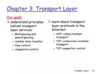
ZXCTN 6100 ( V1.1 ) Packet Transport Product Hardware Introduction. Course Outline. ZXCTN 6100 ( V1.1 ) Product Hardware Introduction Product Overview System Structure Board Function Performance and index. Position of ZXCTN 6100 in the Transmission Network. Access Layer.

E N D
ZXCTN 6100(V1.1)Packet Transport Product Hardware Introduction
Course Outline • ZXCTN 6100(V1.1) Product Hardware Introduction • Product Overview • System Structure • Board Function • Performance and index
Position of ZXCTN 6100 in the Transmission Network Access Layer Convergence Layer Core Layer CTN 6200 NodeB CTN 9004 CTN 6300 CTN 6200 NodeB MSC CTN 6100 RNC CTN 9008 BTS MGW MSTP Access Ring SGSN BSC NodeB MSTP Convergence Layer BTS • ZXCTN 6100 is a carrier-class multi-service carrier product introduced by ZTE , orienting the packet transport. • It focuses on bearing and transmission of integrated mobile backhaul and multi-service network, which can meet transmission requirements of various access layer services.
ZXCTN 6100 brief introduction 1U • Dimensions: 482.6mm(W) X 43.6mm(H) X 225.0mm(D) • Satisfies the mounting requirements of subrack in the IEC standard cabinet (19–inch cabinet) or ETS standard cabinet (21–inch cabinet) • Mounting mode.: wall-mounted mounting mode、cabinet、 desk mounting mode。 • The system adopts the centralized architecture. • Subrack adopts the crosswise structure: main control board+service board • Multi-service bearing throughPWE3:support TDM、ATM/IMA、FE、GE service interfaces • Switch capacity (dual-direction): 6Gbps • Packet transmit rate:7.44Mpps • Equipment power consumption : ≤ 45W • Provides two channels of GE interface and the 1st and 2nd channel of FE interface synchronization Ethernet clock. • Earthquake-proof level: safe under level-9 earthquake
ZXCTN 6100 provides access and transmission of packet service 、TDM service、 perfect service protection、OAM、clock synchronization and has carrier-class service transmission characteristics. Adopts the MPLS-TP network technology. Supports the Ethernet network and ML-PPP E1. Capability of transporting multiple services such as Ethernet service, TDM E1 service, and Asynchronous Transfer Mode (ATM) service. Provides guaranteed QoS. System protection switching time is less than 50 ms. Process the 1PPS/TOD of the clock signal, as well as the PTP protocol. Supports the MPLS-TP OAM and Ethernet OAM functions. Meets the E-Line, E-LAN, and E-Tree service models defined by Metro Ethernet Forum (MEF). Supports various L2 VPN service types. Transport the synchronous clock and time data required by the 2G/3Gmobile communication base station. ZXCTN 6100 System Applications
As the equipment on the access layer, ZXCTN 6100 is applicable to various solutionsand corresponding application scenarios: Access and transport of mobile base station service Access and transport of large client private line service Access and transport of Next Generation Network (NGN) service Access and transport of Internet Protocol Television (IPTV) service Access and transport of Video On Demand (VOD)/Voice over IP (VoIP) service Access and transport of mass client Internet service ZXCTN 6100 Application Scenario
Course Outline • ZXCTN 6100(V1.1) Product Hardware Introduction • Product Overview • System Structure • Board Function • Performance and index
ZTE PTN Product Structure Management plane Control plane E1/STM-N Data plane Packets exchange core TDM PWE3 E1/STM-N IMA E1/ATM STM-N ATM PWE3 GE/10GE FE/GE/10GE ETH PWE3 Clock/time sync (Ethernet clock sync, 1588 time sync) • Three planes of data, control, and management are independently designed. • Packet exchange core, multi-service bearing • Supporting clock/time sync satisfies clock/time requirements in various types of application environments.
ZXCTN 6100 adopts centralized structure. With main board to be the core, system integrates main control, switching and clock functions and transmits service signals and manages data through bus and other components. Different service boards can be inserted into service slots of the system and thusprovide various service interfaces. System adopts centralized power supply. The system power supply boardprovides voltage output to the main control board and fan. System Components
Services and Functions • Service Processing Model
ZXCTN 6100 Subrack 1. Mounting flange 2. Fan area 3. Power supply board area 4. Grounding terminal ofsubrack protection ground 5. Antistatic wrist strap jack 6. Main Control board area 7. Service board area • ZXCTN 6100 subrack adopts the crosswise and horizontal plug-in structure; • Each subrack provides four slots: one main control board slot, two service board slots, and one power supply board slot; • A service board is installed on the main board socket as the sub-board. Compared with the traditional backplane connection mode, a service board nests on the main control board; • Satisfies the mounting requirements of Subrack in the IEC standard cabinet (19–inch cabinet) or ETS standard cabinet (21–inch cabinet); • Can be mounted in cabinet , wall-mounted mounting mode and desk mounting mode;
Board Slots in Subrack • POWER:one power supply board slot • FAN: beside the power supply board • Solt3:one main control board slot • Solt1~Solt2:two interface boards slot
Course Outline • ZXCTN 6100(V1.1) Product Hardware Introduction • Product Overview • System Structure • Board Function • Performance and index
Functions As the core of the equipment, SMB board implements service switching and equipment control. SMBboard consists of the following functional units: CPU unit Packet switching unit Ethernet processing unit Ethernet OAM unit Clock unit Power supply unit Main Control Board SMB
Functional Block Diagram of SMB Main Control Board SMB
Front Panel Main Control Board SMB 1. Ring-trip button (B.OFF) 2. Reset button (N.RST) 3. Board alarm indicator (MAJ/MIN) 4. Board running indicator (RUN) 5. GE Ethernet optical interface 6. Running indicator of Ethernet optical interface (LA) 7. Signal indicator of Ethernet optical interface (SD) 8. BITS interface (Rx) 9. BITS interface (Tx) 10. EMS interface (Qx) 11. Local craft terminal interface (LCT) 12. Alarm output and equipment debugging interface (OUT) 13. Alarm input interface (IN) 14. Equipment clock indicator (STA) 15. Time interface (GPS) 16. Fast Ethernet electrical interface (FE) 17. Running indicator of Ethernet electrical interface (LA) 18. Rate indicator of Ethernet electrical interface (SP) 19. Grounding terminal of equipment protection ground 20. Antistatic wrist strap jack (ESD)
Interface Main Control Board SMB
Board Indicator Status Main Control Board SMB • “Flashes (0.5 time/second)” means that the indicator is on for one second and off for another one second. • “Flashes (1 time/second)” means that the indicator is on for half a second and off for another half a second. • “Flashes (5 times/second)” means that the indicator is on for 0.1 second and off for another 0.1 second.
GE Corresponding Relationship between Optical Interface Indicators and Interface Statuses Main Control Board SMB • “-” indicates uncertain status. • “Flashes (5 times/second)” means that the indicator is on for 0.1 second and off for another 0.1 second.
FE Corresponding Relationship between Optical Interface Indicators and Interface Statuses Main Control Board SMB • “-” indicates uncertain status. • “Flashes (5 times/second)” means that the indicator is on for 0.1 second and off for another 0.1 second.
Functions Each E1 interface mode can be configured as CircuitEmulation Services (CES), IMA, or ML-PPP. When E1 interface works in CES service mode, itsupports structured and non-structured TDM E1 services. If itsupport structured services, it supports tE1 framing processingand timeslot compression function. The first two E1 interfaces can extract the clock, and then send the extracted timing clock to the clock unit of the main control board. All the 16 E1 tributaries support the retiming function. Supports the adaptive clock restoration and the CES output clock wander control. If E1 interface works in the ML-PPP service mode, it canseparately carry the voice and signaling services of base stations. Supports extracting the synchronous clock from the line. Supports detection of the ML-PPP link status. Supports protection for the E1 links in the ML-PPP groups of theboard. Supports performance analysis and alarm detection of E1 signals, report the related information. Encapsulates and decapsulates CES/IMA services into or from PWE3 services. E1 Electrical Tributary Emulation Board E1TE(E1TE-75/E1TE-120) • Notice: • Structured Data Transfer (SDT) circuit emulation • sender drops useless timeslots in data flow, only extracts user-used timeslots from service flow, encapsulates them into PW packets, and sends packets to receiver. Receiver restores service timeslots from PW packets, and restores a complete service flow according to the sequence numbers of timeslots. • Unstructured Data Transfer (UDT) circuit emulation • Not consider the frame boundary, encapsulates data flow (all 64 kbit/s timeslots) into PW packets for transmission.
Front Panel E1TE-75 and E1TE-120 have the same front panel,which areboth identified as E1TEx16. 3 4 1 2 5 E1 Electrical Tributary Emulation Board E1TE(E1TE-75/E1TE-120) 1. Mounting hole 2. E1 electrical interface (channel 1 – channel 8) 3. Board running indicator (RUN) 4. Board alarm indicator (ALM) 5. E1 electrical interface (channel 9 - channel 16)
E1 Electrical Tributary Emulation Board E1TE(E1TE-75/E1TE-120) • Interface • Indicator Status • “Flashes (0.5 time/second)” means that the indicator is on for one second and off for another onesecond.
Gigabit Ethernet Interface Board GEx1 • Functions • GEx1 board is a GE interface board. It provides one GE optical interface with the rateof 1000 Mbit/s. • The detailed functions of GEx1 board are described as follows: • Supports configuration for the interface rate. • Supports digital diagnosis for the optical interface. • Supports automatic laser shutdown of the optical interface. • Supports synchronous Ethernet. • The GE interface supports link aggregation.
Front Panel Gigabit Ethernet Interface Board GEx1 1. Mounting hole 2. Board running indicator (RUN) 3. Board alarm indicator (ALM) 4. GE Ethernet optical interface 5. Running indicator of Ethernet optical interface (LA) 6. Signal indicator of Ethernet optical interface (SD)
Board Indicator Status GEx1OpticalInterface Indicator Status Gigabit Ethernet Interface Board GEx1 • “-” indicates uncertain status. • “Flashes (5 timse/second)” means that the indicator is on for 0.1 second and off for another 0.1 second.
Functions FEx4 board is an Ethernet interface board with four optical interfaces. Employ the SFP optical module, which supports hot plug/unplug and digital variable measurement. Work in the 100 M full duplex mode. Supports automatic negotiation. The first two FE interfaces supports clock restoration from the physical line. All the four FE interfaces support the 1588V2 clock transport protocol. FE Interface Board FEx4
FE Interface Board FEx4 • Front Panel 1. Captive fastener 2. Board running indicator (RUN) 3. Board alarm indicator (ALM) 4. Ethernet optical interface (RXn/TXn,n=1、2、3、4) 5. Running indicator of Ethernet optical interface (LAn,n=1、2、3、4) 6. Signal indicator of Ethernet optical interface (SDn,n=1、2、3、4)
Board Indicator Status FEx4 OpticalInterface Indicator Status FE Interface Board FEx4 • “Flashes (0.5 time/second)” means that the indicator is on for one second and off for another one second. • “Flashes (5 times/second)” means that the indicator is on for 0.1 second and off for another 0.1 second.
Functions DC power supply board (PWA) provides the required DC power for various boards: Channel A accesses the active power supply, while channel Baccesses the standby power supply (such as battery powersupply). Channel A and channel B are 1:1 backup for each other, withonly one channel working. Provides the over-current protection. When the equipment internal current is over the rated current, the PWA board will cut off the internal power supply for the equipment. Detect the over-voltage and under-voltage. When the external power supply voltage is too low, the system will report the under-voltage alarm. When the external power supply voltage is too high, the system will report the over-voltage alarm. DC Power Supply Board PWA
Front Panel DC Power Supply Board PWA 1. Mounting hole 2. Channel A power supplyindicator 3. Channel B power supplyindicator 4. Channel A DC powersocket 5. Power supply switch 6. Channel B DC powersocket 7. Board alarm indicator(ALM) 8. Board running indicator(RUN) • Interface
DC Power Supply Board PWA • Board Indicator Status
Functions AC power supply board (PWB) provides the required AC power for the other boards: Applies to the primary power supply of AC 110 V/220 V. The input voltagefluctuation ranges from 110 V AC to 240 V AC. Provides the over-current protection. When the equipment internal current is over the rated current, the PWA board will cut off the internal power supply for the equipment. Detect the over-voltage and under-voltage. When the external power supply voltage is too low, the system will report the under-voltage alarm. When the external power supply voltage is too high, the system will report the over-voltage alarm. AC Power Supply Board
Front Panel AC Power Supply Board 1. Mounting hole 2. Power supply switch 3. Board alarm indicator(ALM) 4. Board running indicator(RUN) 5. AC power socket • Interface • Board Indicators
Course Outline • ZXCTN 6100(V1.1) Product Hardware Introduction • Product Overview • System Structure • Board Function • Performance and index
Power Indicators Service Performance Reliability Indicators Ethernet Performances Clock Time Performances Protection Switching Performance Interface Performances ZXCTN 6100 (V1.1)Product Performance list
Power Indicators • Power Supply Requirements PWA and PWB can not be used at the same time • Power Consumption Indexes • The overall power consumptions are different according to different configurations and the maximum power consumption is less than 42 W. • The power consumption of ZXCTN 6100 with typical configuration is listed below:
ZXCTN 6100 supports the service switching with packets as core. The service processing capability is shown below: ZXCTN 6100 provides various service interfaces. The types andnumber of interfaces are shown below: Service Performance
Reliability Indicators • ZXCTN 6100 Reliability Indicators
Ethernet Performances • Basic Ethernet Performance
Quantity of VLANID All Ethernet interfaces of ZXCTN 6100 can identify C-VLANID 1-4094 according to IEEE 802.1Q ,and VLAN ID 1-4094 can beconfigured on all Ethernet interfaces. Quality of Ethernet EVC Services Ethernet Performances
MAC Address Performance ACL and other Performance Ethernet Performances
Route Performance MPLS-TP Performance Ethernet Performances
Synchronous Clock Source system provides 10 synchronous clock sourcesat most. SMB board provides: 1 GPS interface synchronous clock source 1 BITS interface synchronous clock source 2 FE interface synchronous clock sources (thefirst two) 2 GE interface synchronous clock sources Service card slot provides: Each slot provides 2 synchronous clock sources (the first two) ZXCTN 6100 subrack provides 1 SMB card slot and 2 service card slots. Clock Synchronization Performances ZXCTN 6100 clock synchronization performances meet requirements of the following standards: YD1011(1999) YD1012(1999) ITU-T G.810(1996–08) ITU-T G.812(2004–06) ITU-T G.813(2003–03) ITU-T G.823(2000–03) Clock Time Performances
Time Synchronization Performances 1588 TimePerformances Timer Precision:timeslot unit of IEEE 1588 absolute time timer withinZXCTN 6100 system is ns and the worst timer precisionis 10ns. Time Transfer Precision:In the time transfer network composed by ZXCTN 6100systems, all nodes synchronize clocks through synchronousEthernet or other modes. The difference of absolute timetransfer is less than 1us after master and slave interfaces of10 nodes synchronize their clocks. GPS ClockPerformances ZXCTN 6100 supports 1 input and output of phase synchronizationinformation (1PPS) and absolute time P2P time transfer is tested in the network with at least 30 border clock nodes. Clock Time Performances
Time Synchronization Performances Clock Time Performances