Download

1 / 108
1.31k likes | 1.8k Vues
Princess Sumaya University for Technology. Computer Organization and Architecture I. Introduction to Verilog Hardware Description Language. Dr. Esam Al- Qaralleh. Introduction. Purpose of HDL: Describe the circuit in algorithmic level (like c) and in gate-level (e.g. And gate) Simulation

E N D
Princess Sumaya University for Technology Computer Organization and Architecture I Introduction to Verilog Hardware Description Language Dr. Esam Al-Qaralleh
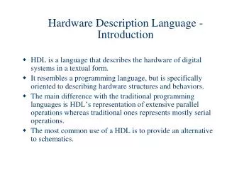
Introduction Purpose of HDL: • Describe the circuit in algorithmic level (like c) and in gate-level (e.g. And gate) • Simulation • Synthesis • Words are better than pictures Dr. Esam Al-Qaralleh
The best way to describe a circuit? If both inputs are 1, change both outputs. If one input is 1 change an output as follows: If the previous outputs are equal change the output with input 0; If the previous outputs are unequal change the output with input 1. If both inputs are 0, change nothing. Dr. Esam Al-Qaralleh
Verilog Basics Dr. Esam Al-Qaralleh
helloWorld.v module helloWorld ; initial begin $display ("Hello World!!!"); $finish; end endmodule Modules are the unit building-blocks (components) Verilog uses to describe an entire hardware system. Modules are (for us) of three types: behavioral, dataflow, gate-level. We ignore the switch-level in this course. This module is behavioral. Behavioral modules contain code in procedural blocks. System calls. This is a procedural block. There are two types of procedural blocks: initial and always. More than one statement must be put in a begin-end group.
Module declaration Module Input Circuit X Wire Y Output Z O Dr. Esam Al-Qaralleh
Module declaration Module Input Circuit Module name X Wire Y modulesample (X,Y,Z,O); input X,Y,Z; output O; // Describe the circuit using logic symbols assign O = (X^Y)&Z; endmodule Output Z O Dr. Esam Al-Qaralleh
Typical Module Components Diagram Module name, Port list (optional, if there are ports) Port declarations Parameter list Declaration of variables (wires, reg, integer etc.) Instantiation of inner (lower-level) modules Structural statements (i.e., assign and gates) Procedural blocks (i.e., always and initial blocks) Tasks and functions endmodule declaration
Lexicography • Comments: Two Types: • // Comment • /*These comments extend over multiple lines. Good for commenting out code*/ • Character Set: 0123456789ABCD..YZabcd...yz_$ Cannot start with a number or $ Dr. Esam Al-Qaralleh
systemCalls.v module systemCalls(clk); input clk; clockGenerator cg(clk); initial begin #25 $stop; #50 $finish; end initial begin $write("$write does not "); $write("add a new line\n"); $display("$display does"); $display("add a new line"); $monitor("Clock = %d", cg.clk); end endmodule Compile with the clockGenerator.v module. Suspends simulation – enters interactive mode. Terminates simulation. Similar output calls except $display adds a new line. $monitor produces output each time a variable changes value.
Data Types • Nets and Registers • Vectors • Integer, Real, and Time Register Data Types • Arrays • Memories • Parameters • Strings Verilog HDL
Nets • Used to represent connections between HW elements • Values continuously driven on nets • Keyword: wire • Default: One-bit values • unless declared as vectors • Default value: z • For trireg, default is x • Examples • wire a; • wire b, c; • wire d=1’b0; Verilog HDL
Registers • Registers represent data storage elements • Retain value until next assignment • NOTE: this is not a hardware register or flipflop • Keyword: reg • Default value: x • Example: reg reset; initial begin reset = 1’b1; #100 reset=1’b0; end Verilog HDL
Vectors • Net and register data types can be declared as vectors (multiple bit widths) • Syntax: • wire/reg [msb_index : lsb_index] data_id; • Example wire a; wire [7:0] bus; wire [31:0] busA, busB, busC; reg clock; reg [0:40] virtual_addr; Verilog HDL
Vectors (cont’d) • Consider wire [7:0] bus; wire [31:0] busA, busB, busC; reg [0:40] virtual_addr; • Access to bits or parts of a vector is possible: busA[7] bus[2:0] // three least-significant bits of bus // bus[0:2] is illegal. virtual_addr[0:1] /* two most-significant bits * of virtual_addr */ Verilog HDL
Integer, Real, and Time Register Data Types • Integer • Keyword: integer • Very similar to a vector of reg • integer variables are signed numbers • reg vectors are unsigned numbers • Bit width: implementation-dependent (at least 32-bits) • Designer can also specify a width: integer [7:0] tmp; • Examples: integer counter; initial counter = -1; Verilog HDL
Integer, Real, and Time Register Data Types (cont’d) • Real • Keyword: real • Values: • Default value: 0 • Decimal notation: 12.24 • Scientific notation: 3e6 (=3x10⁶) • Cannot have range declaration • Example: real delta; initial begin delta=4e10; delta=2.13; end integer i; initial i = delta; // i gets the value 2 (rounded value of 2.13) Verilog HDL
Integer, Real, and Time Register Data Types (cont’d) • Time • Used to store values of simulation time • Keyword: time • Bit width: implementation-dependent (at least 64) • $time system function gives current simulation time • Example: time save_sim_time; initial save_sim_time = $time; Verilog HDL
Arrays • Only one-dimensional arrays supported • Allowed for reg, integer, time • Not allowed for real data type • Syntax: <data_type> <var_name>[start_idx : end_idx]; • Examples: integer count[0:7]; reg bool[31:0]; time chk_point[1:100]; reg [4:0] port_id[0:7]; integer matrix[4:0][4:0]; // illegal count[5] chk_point[100] port_id[3] • Note the difference between vectors and arrays Verilog HDL
Memories • RAM, ROM, and register-files used many times in digital systems • Memory = array of registers in Verilog • Word = an element of the array • Can be one or more bits • Examples: reg membit[0:1023]; reg [7:0] membyte[0:1023]; membyte[511] • Note the difference (as in arrays): reg membit[0:127]; reg [0:127] register; Verilog HDL
Data Types ~ summary • Data Values: 0,1,x,z • Wire • Synthesizes into wires • Used in structural code • Reg • May synthesize into latches, flip-flops or wires • Used in procedural code • Integer 32-bit integer used as indexes • Input, Output, inout Defines ports of a module (wire by default) module sample (a,b,c,d); input a,b; output c,d; wire [7:0] b; reg c,d; integer k; Dr. Esam Al-Qaralleh
4valuedLogic.v module fourValues( a , b, c, d ); output a, b, c, d ; assign a = 1; assign b = 0; assign c = a; assign c = b; endmodule module stimulus; fourValues X(a, b, c, d); initial begin #1 $display("a = %d b = %d, c = %d, d = %d", a, b, c, d); $finish; end endmodule Conflict or race condition. Remember this is not a procedural (i.e., sequential) block! These are continuous assign- ments. 4-valued logic: 0 – low 1 – high x – unknown z – undriven wire Now explain output!
Data Values • Numbers: Numbers are defined by number of bits Value of 23: 5’b10111 // Binary 5’d23 // Decimal 5’h17 // Hex • Constants: wire [3:0] t,d; assign t = 23; assign d= 4’b0111; • Parameters: parameter n=4; wire [n-1:0] t, d; `define Reset_state = 0, state_B =1, Run_state =2, finish_state = 3; if(state==`Run_state) Dr. Esam Al-Qaralleh
numbers.v Register array. module numbers; integer i, j; reg[3:0] x, y; initial begin i = ‘b1101; $display( "decimal i = %d, binary i = %b", i, i ); $display( "octal i = %o, hex i = %h", i, i ); j = -1; $display( "decimal j = %d, binary j = %b", j, j ); $display( "octal j = %o, hex j = %h", j, j ); x = 4'b1011; $display( "decimal x = %d, binary x = %b", x, x ); $display( "octal x = %o, hex x = %h", x, x ); y = 4'd7; $display( "decimal y = %d, binary y = %b", y, y ); $display( "octal y = %o, hex y = %h", y, y ); $finish; end endmodule ‘<base>: base can be d, b, o, h Array of register arrays simulate memory. Example memory declaration with 1K 32-bit words: reg[31:0] smallMem[0:1023]; Default base: d Negative numbers are stored in two’s complement form. Typical format: <size>’<base><number> size is a decimal value that specifies the size of the number in bits.
Operators • Arithmetic: *,+,-, /,% • Relational <,<=,>,>=,==, != • Bit-wise Operators • Not: ~ • XOR: ^ • And : & 5’b11001 & 5’b01101 ==> 5’b01001 • OR: | • XNOR: ~^ or ^~ • Logical Operators Returns 1or 0, treats all nonzero as 1 • ! : Not • && : AND 27 && -3 ==> 1 • || : OR reg [3:0] a, b, c, d; wire[7:0] x,y,z; parameter n =4; c = a + b; d = a *n; If(x==y) d = 1; else d =0; d = a ~^ b; if ((x>=y) && (z)) a=1; else a = !x; Dr. Esam Al-Qaralleh
Operators • Reduction Operators: Unary operations returns single-bit values • & : and • | :or • ~& : nand • ~| : nor • ^ : xor • ~^ :xnor • Shift Operators Shift Left: << Shift right: >> • Concatenation Operator { } (concatenation) { n{item} } (n fold replication of an item) • Conditional Operator Implements if-then-else statement (cond) ? (result if cond true) : (result if cond false) module sample (a, b, c, d); input [2:0] a, b; output [2;0] c, d; wire z,y; assign z = ~| a; c = a * b; If(a==b) d = 1; else d =0; d = a ~^ b; if ((a>=b) && (z)) y=1; else y = !x; assign d << 2; //shift left twice assign {carry, d} = a + b; assign c = {2{carry},2{1’b0}}; // c = {carry,carry,0,0} assign c= (inc==2)? a+1:a-1; Dr. Esam Al-Qaralleh
clockGenerator.v Port list. Ports can be of three types: input, output, inout. Each must be declared. module clockGenerator(clk); output clk; reg clk; initial begin clk = 0; end always #5 clk = ~clk; endmodule Internal register. Register reg data type can have one of four values: 0, 1, x, z. Registers store a value till the next assignment. Registers are assigned values in procedural blocks. If this module is run stand-alone make sure to add a $finish statement here or simulation will never complete! The delay is half the clock period.
Verilog Structure • All code are contained in modules • Can invoke other modules • Modules cannot be contained in another module module gate(Z,A,B,C); input A,B,C; output Z; assign Z = A|(B&C); Endmodule module two_gates(Z2,A2,B2,C2) input A2,B2,C2; output Z2; gate gate_1(G2,A2,B2,C2); gate gate_2(Z2,G2,A2,B2); endmodule Dr. Esam Al-Qaralleh
Structural Vs Procedural Structural • textual description of circuit • order does not matter • Starts with assign statements • Harder to code • Need to work out logic Procedural • Think like C code • Order of statements are important • Starts with initial or always statement • Easy to code • Can use case, if, for reg c, d; always@ (a or b or c) begin c =a & b; d = c |b; end wire c, d; assign c =a & b; assign d = c |b; Dr. Esam Al-Qaralleh
Structural Vs Procedural Procedural reg [3:0] Q; wire [1:0] y; always@(y) begin Q=4’b0000; case(y) begin 2’b00: Q[0]=1; 2’b01: Q[1]=1; 2’b10: Q[2]=1; 2’b11: Q[3]=1; endcase end Structural wire [3:0]Q; wire [1:0]y; assign Q[0]=(~y[1])&(~y[0]), Q[1]=(~y[1])&y[0], Q[2]=y[1]&(~y[0]), Q[3]=y[1]&y[0]; Dr. Esam Al-Qaralleh
Blocking Vs Non-Blocking Non-blocking • <variable> <= <statement> • The inputs are stored once the procedure is triggered • Statements are executed in parallel • Used for flip-flops, latches and registers Blocking • <variable> = <statement> • Similar to C code • The next assignment waits until the present one is finished • Used for combinational logic Do not mix both assignments in one procedure Dr. Esam Al-Qaralleh
Blocking Vs Non-Blocking Initial begin #1 e=2; #1 b=1; #1 b<=0; e<=b; // grabbed the old b f=e; // used old e=2, did not wait e<=b Dr. Esam Al-Qaralleh
blockingVSnba1.v module blockingVSnba1; integer i, j, k, l; initial begin #1 i = 3; #1 i = i + 1; j = i +1; #1 $display( "i = %d, j = %d", i, j ); #1 i = 3; #1 i <= i + 1; j <= i + 1; #1 $display( "i = %d, j = %d", i, j ); $finish; end endmodule Blocking (procedural) assignment: the whole statement must execute before control is released, as in traditional programming languages. Non-blocking (procedural) assignment: all the RHSs for the current time instant are evaluated (and stored transparently in temporaries) first and, subsequently, the LHSs are updated at the end of the time instant.
blockingVSnba2.v module blockingVSnba2(clk); input clk; clockGenerator cg(clk); integer i, j; initial begin i = 10; #50 $finish; end always @(posedge clk) i = i + 1; // i <= i + 1; always @(posedge clk) j = i; // j <= i; always @(negedge clk) $display("i = %d, j = %d", i, j); endmodule Compile with clockGenerator.v. An application of non-blocking assignments to solve a race problem. • With blocking assignments we get different output • depending on the order these two statements are • executed by the simulator, though they are both • supposed to execute “simultaneously” at posedge clk • race problem. • Race problem is solved if the non-blocking • assignments (after the comments) are used instead • - output is unique.
blockingVSnba3.v module blockingVSnba3; reg[7:0] dataBuf, dataCache, instrBuf, instrCache; initial begin dataCache = 8'b11010011; instrCache = 8'b10010010; #20; $display("Time = %d, dataBuf = %b, instrBuf = %b", $time, dataBuf, instrBuf); dataBuf <= #1 dataCache; instrBuf <= #1 instrCache; #1 $display("Time = %d, dataBuf = %b, instrBuf = %b", $time, dataBuf, instrBuf); $finish; end endmodule The most important application of non-blocking assignments is to model concurrency in hardware systems at the behavioral level. Both loads from dataCache to dataBuf and instrCache to instrBuf happen concurrently in the 20-21 clock cycle. Replace non-blocking with blocking assignments and observe.
System Tasks and Compiler Directives
System Tasks • System Tasks: standard routine operations provided by Verilog • Displaying on screen, monitoring values, stopping and finishing simulation, etc. • All start with $ Verilog HDL
System Tasks (cont’d) • $display: displays values of variables, strings, expressions. • Syntax: $display(p1, p2, p3, …, pn); • p1,…, pn can be quoted string, variable, or expression • Adds a new-line after displaying pn by default • Format specifiers: • %d, %b, %h, %o: display variable respectively in decimal, binary, hex, octal • %c, %s: display character, string • %e, %f, %g: display real variable in scientific, decimal, or whichever smaller notation • %v: display strength • %t: display in current time format • %m: display hierarchical name of this module Verilog HDL
System Tasks (cont’d) • $display examples: • $display(“Hello Verilog World!”); Output:Hello Verilog World! • $display($time); Output:230 • reg [0:40] virtual_addr; • $display(“At time %d virtual address is %h”, $time, virtual_addr); Output:At time 200 virtual address is 1fe000001c Verilog HDL
System Tasks (cont’d) • reg [4:0] port_id; • $display(“ID of the port is %b”, port_id); Output:ID of the port is 00101 • reg [3:0] bus; • $display(“Bus value is %b”, bus); Output:Bus value is 10xx • $display(“Hierarchical name of this module is %m”); Output:Hierarchical name of this module is top.p1 • $display(“A \n multiline string with a %% sign.”); Output:A multiline string with a % sign. Verilog HDL
System Tasks (cont’d) • $monitor: monitors a signal when its value changes • Syntax: $monitor(p1, p2, p3, …, pn); • p1,…, pn can be quoted string, variable, or signal names • Format specifiers just as $display • Continuously monitors the values of the specified variables or signals, and displays the entire list whenever any of them changes. • $monitor needs to be invoked only once (unlike $display) • Only one $monitor (the latest one) can be active at any time • $monitoroff to temporarily turn off monitoring • $monitoron to turn monitoring on again Verilog HDL
System Tasks (cont’d) • $monitor Examples: initial begin $monitor($time, “Value of signals clock=%b, reset=%b”, clock, reset); end • Output:0 value of signals clock=0, reset=15 value of signals clock=1, reset=110 value of signals clock=0, reset=0 Verilog HDL
System Tasks (cont’d) • $stop: stops simulation • Simulation enters interactive mode when reaching a $stop system task • Most useful for debugging • $finish: terminates simulation • Examples: initial begin clock=0; reset=1; #100 $stop; #900 $finish; end Verilog HDL
Compiler Directives • General syntax: `<keyword> • `define: similar to #define in C, used to define macros • `<macro_name> to use the macro defined by `define • Examples: `define WORD_SIZE 32 `define S $stop `define WORD_REG reg [31:0] `WORD_REG a_32_bit_reg; Verilog HDL
Compiler Directives (cont’d) • `include: Similar to #include in C, includes entire contents of another file in your Verilog source file • Example: `include header.v ... <Verilog code in file design.v> ... Verilog HDL
simpleBehavioral.v Sensitivity trigger: when any of a, b or c changes. Replace this statement with “initial”. Output?! module aOrNotbOrc(d, a, b, c); output d; input a, b, c; reg d, p; always @(a or b or c) begin p = a || ~b; d = p || c; end endmodule Modules are of three types: behavioral,dataflow, gate-level. Behavioral modules contain code in procedural blocks. Statements in a procedural block cannot be re-ordered without affecting the program as these statements are executed sequentially, exactly like in a conventional programming language such as C. Ports are of three types: input, output, inout. Each must be declared. Each port also has a data type: either reg or wire (net). Default is wire. Inputs and inouts are always wire. Output ports that hold their value are reg, otherwise wire. More later… One port register, one internal register. Wires are part of the more general class of nets. However, the only nets we shall design with are wires.
simpleBehavioral.v (cont.)Top-level stimulus module module stimulus; integer i, j, k; reg a, b, c; aOrNotbOrc X(d, a, b, c); initial begin for ( i=0; i<=1; i=i+1 ) for ( j=0; j<=1; j=j+1 ) for ( k=0; k<=1; k=k+1 ) begin a = i; b = j; c = k; #1 $display("a = %d b = %d, c = %d, d = %d", a, b, c, d) end $finish; end endmodule Verilog Good Design Principle There is one top-level module, typically called system or stimulus, which is uninstantiated and has no ports. This module contains instantiations of lower-level (inner) sub-modules. Typical picture below. Instantiation. Top-level module Inner sub-modules Remove the #1 delay. Run. Explain!
Port Rules Diagram Outside connectors to internal ports, i.e., variables corresponding to ports in instantiation of internal module wire EXTERNAL MODULE wire Example: module external reg a; wire b; internal in(a, b); //instantiation … endmodule module internal(x, y) input x; output y; wire x; reg y; … endmodule wire inout Internal ports input output port-connector reg or wire wire reg or wire INTERNAL MODULE General rule (with few exceptions) Ports in all modules except for the stimulus module should be wire. Stimulus module has registers to set data for internal modules and wire ports only to read data from internal modules.
If Statements Syntax if (expression) begin ...statements... end else if (expression) begin ...statements... end ...more else if blocks else begin ...statements... end Dr. Esam Al-Qaralleh