Verilog Hardware Description Language
Verilog Hardware Description Language. Sections in Chapter 3-9 Digital Design, 4 th Edition M. Morris Mano and micchael D. Ciletti. Introduction. HDL stands for Hardware Description Language Used to describe digital system in textual form


Verilog Hardware Description Language
E N D
Presentation Transcript
Verilog Hardware Description Language Sections in Chapter 3-9 Digital Design, 4th Edition M. Morris Mano and micchael D. Ciletti
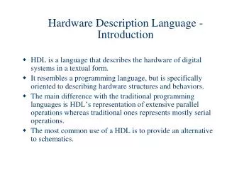
Introduction • HDL stands for Hardware Description Language • Used to describe digital system in textual form • Oriented to the structure and behaviour of digital systems • Verilog HDL programs can be read by both human and computer • Tow main applications of HDL • Logic Simulation • Logic Synthesis 2
Logic Simulation • Representation of structure and behaviour of digital systems using computer • The simulator interrupts the HDL description and produce readable output (table, timing diagram, ..) • This process help in predicting how digital system will behave before fabrication • The stimulus that test the design is called Test Bench (written in HDL) • To simulate a digital system:- • Write the HDL description for the system • Verify using Test Bench 3
Logic Synthesis • Driving a list of components and its interconnection (net list) from a module described in HDL • Used to fabricate integrated circuits or printed circuit board • Same as conventional high level language, the difference is it produce a database with instruction how to fabricate the physical piece of the digital system Source Code Object Code Conventional Lang Compilation 4
Logic Synthesis (continue) Source Code Database with Instruction to Fabricate system Logic Synthesis Compilation 5
Historical Background • Two main standard supported by IEEE • VHDL • Verilog HDL VHDL • Developed by Department of defense • Like AdaProgramming language Verilog HDL • By Cadence Data System (late1990) • Easier than VHDL, like C language 6
Simple Verilog HDL Example #1 Write a verilog HDL description for the following circuit using gate level module or_nand_1 (enable, x1, x2, x3, x4, y); inputenable, x1, x2, x3, x4; outputy; wirew1, w2, w3; or(w1, x1, x2); or(w2, x3, x4); or(w3, x3, x4); // redundant nand(y, w1, w2, w3, enable); endmodule 7
Simple Verilog HDL Example #2 Write a verilog HDL description for the following circuit using Data flow module or_nand_2 (enable, x1, x2, x3, x4, y); inputenable, x1, x2, x3, x4; outputy; assigny = !(enable & (x1 | x2) & (x3 | x4)) endmodule 8
Simple Verilog HDL Example #3 Write a verilog HDL description for the following circuit using behavioral module or_nand_3 (enable, x1, x2, x3, x4, y); inputenable, x1, x2, x3, x4; outputy; regy; always@(enable orx1 or x2 orx3 orx4) if(enable) y = !((x1 | x2) & (x3 | x4)); else y = 1; // operand is a constant. endmodule 9
Structure of Verilog HDL description • Module is the building block • Every module declared by moduleand terminated byendmodule • Module look like module module_name ( port_list ); port declarations;// input, output variable declaration;// wire, reg … description of behavior // instantiation, // statements endmodule 10
Verilog basic concepts Keyword in Verilog • About 100 keyword • Must be in lowercase (case sensitive) • Examples of keywords are:- module, input, reg, and, for, else, not, if, case, always, nand, wire, endmodule, …. Comments in Verilog • // single line • /* multiple lines */ 11
Verilog basic concepts (continue) Identifiers in verilog • May begin with alphabetic or underscore • May contain:- • digits 0 – 9, $, 0r _ Logic values • Verilog has 4 logic values • logic 0, logic 1 • z or Z high impedance • x or X unknown 12
Verilog basic concepts (continue) Number specification • Two types of number specification:- • Sized and unsized Sized numbers • General form:- size ‘base value • Size is written in decimal, specify # of bits • Base, format is:- • d or D, for decimal, example 5 ‘d 132 (5-bits) • b or B, for binary, example 4 ‘b 1011 (4-bits) • o or O, for octal, example 5 ‘o 132 (5-bits) • h or H, for hex, example 12 ‘h a45c (12-bits) 13
Verilog basic concepts (continue) • The size is optional, default is 32-bits • The base is optional, default is decimal Unsized numbers • Without base format • example ‘h 3b (32-bits hex) • 45678 ( 32-bits decimal by default ) X and Z values • Denoted by x (unknown) and z (high imp) • 8’h5x, 8-bits hex number; 4 LSB are unknown 14
Verilog basic concepts (continue) Arithmetic operators • Two types: binary and unary (sign; + & -) • +, -, * , /, and % (Modulus) Example if A = 4 ‘b0011 and B = 4’b 0100, then • A + B = 4’b0111 • B - A = 4’b0001 • 3 + 7 = 10 (decimal) • 5% 2 = 1 (decimal) • - 4 Negative 4 (unary) 15
Verilog basic concepts (continue) Bitwise Operators • ~ (inverting), & (AND), | (OR), ^ (XOR), ^~ or ~^ (XNOR) • Performed a bit-by-bit operation on two operands (corresponding bits ) • If one operand is shorter than the other, it will be extended with 0’s to match longer Example if A = 4 ‘b0011 and B = 4’b 0101, then • Y = ~A; Y = 4’b 1100 • X = A & B; X = 4’b 0001 • Z = A ^ B; Z = 4’b 0110 16
Verilog basic concepts (continue) Reduction Operator • Are:- & (AND),| (OR), ^ (XOR), ^~ or ~^ (XNOR) but on one operand, yield to 1-bit • Work bit by bit from right to left Example if A = 4 ‘b0011, then • Y = &A; Y=’b 0, equivalent to (0 & 0 & 1 & 1) Logical Operators • ! (NOT (unary)), && (AND), || (OR), 17
Verilog basic concepts (continue) • Evaluate to 1-bit, false (0), true(1), or x • Non zero is logic 1, and zero is logic 0 • Operands can be :- values or expression Example if A = 4 and B = 0, then • Y = A && B; Y = 0 • X = A || B; X = 1 NoteDo not confuse between Bitwise, reduction and logical operators 18
Verilog basic concepts (continue) Relational operators • > (grater), >=(grater or equal), <(less than),<=(less or equal) • Evaluate to true (1) or false (0) Example if A = 4, B = -2, C= 3’b001, and D=3’b1xz then • Y = A > B; Y = 1 • X = C <= D ; X = x (any x or z bits in the operand, the result is x) 19
Verilog basic concepts (continue) Equality Operators • == (equal to),!= (not equal to),=== (case equal to), !== (case not equal to) • == and != yield to 1, 0, or x(if operand has x or z bits) • === and !== yield to 1 or 0 • Compare both operand bit by bit including x and z, result is 1 if complete match Example if A = 3’b0xz, and B=3’b1xz, then • Y = A == B; Y = x • X = A === B ; X = 0 20
Verilog basic concepts (continue) Logical shift operators • << (shift left) and >> (shift right) Example if x= 5’b01110, then • Y = x >> 2, y = 5’b00011 • Y = x << 1, y = 5’b11100 Concatenation Operator • {m , n} means concatenate m to n • Operands must sized 21
Verilog basic concepts (continue) Example if A = 4 ‘b0011 and B = 4’b 0100, then • Y = {A,B}, Y = 8’b00110100 • Y = {010,B}, Y = 7’b0100100 Replication operator • Replicate concatenation a number of time • { 3{m}}, replicate m operand 3 times Example • Y = {3{01}}, Y = 010101 • Y = {3{01}, 2{10}}, Y = 0101011010 22
Verilog basic concepts (continue) Conditional Operator • ?: , takes three operands • Syntax Cond_exp ? T_exp : F_exp, • Evaluate Cond_exp, if:- • True select T_exp • False select F_exp Example read a value for mark, then • Grade =mark >= 60 ?pass : fail • if mark = 70 (say), then Grade = pass 23
HDL For Combinational Circuits • A module is described in any one (or combination) of the following techniques:- Gate-Level modeling:- Instantiation of primitive gates and user-defined module Dataflow modeling:- Using continuous assignment statements with the keyword assign Behavioral modeling:- Using procedural statements with the keyword always 24
Gate-Level Modeling • Describe the circuit by specifying gates and their interconnection • Provide textual description of a schematic • Verilog recognize 12 basic gates • 4 are of 3-state type (see fig 4-31) • Other 8 gates are :-and, or, nand, nor, xnor, xor, not, buf • When the gates are simulated, the system assign a 4-valued logic set to each gate • 0, 1, X, when I/P or O/P is ambiguous (not 0 or 1 ), z, occurs in O/P of a 3-starte gate or if the wire is unintentionally left unconnected 25
Gate-Level Modeling (continue) • O/P of a gate is evaluated as soon as one of the I/P’s changed • Table 4.9 shows truth table for:- and, or, xor, not gates • and & or truth tables are shown below 26
Gate-Level Modeling (continue) • When a primitive gate is incorporated in a module, we say it is instantiated in the module Instances • Instantiation is the process of creating actual objects from module template • When module is invoked, HDL creates unique objects (copies) called instance 27
Gate-Level Modeling (continue) module muxor_4_1 (A,B, c0, c1, c2, c3, y); inputA,B, c0, c1, c2, c3; outputY; wirea_inv,b_inv, y0, y1, y2, y3; not(a_inv, A); not(b_inv, B); and (y0,c0,a_inv,b_inv); and (y1,c1,a_inv,B); and (y2,c2,A,b_inv); 28
Gate-Level Modeling (continue) and (y3,c3,A,B); or(Y, y0,y1,y2,y3); endmodule Gate instantiation • Without instance name • and (y3,c3,A,B); • With instance name • and G1 (y3,c3,A,B); • Both are legal in Verilog HDL 29
Gate-Level Modeling (continue) Gate delay • In real circuits, logic gate have delay • Gate delay is specified by # (value) Example module half_adder_gates(x,y,sum,carry); inputx, y; output sum, carry; and #(10) (carry, x, y);//10 unitdelay xor u_sum #(5) (sum, x, y);//5unit ,, endmodule 30
User-Define Primitive (UDP) • Logic gates (and, or, …) used in HDLare define by the system are referred to as system primitive(built in primitive) • User can create additional primitives by defining them in a tabular form (Truth table), referred to as UDP • UDP is declared by the keyword primitive • UDP take only scalar I/P terminals (1 bit) • UDP can have only 1 scalar O/P terminal • In sequential UDP, O/P must be declared as reg (since sequential UDP store state) 31
User-Define Primitive (continue) Example (Design a half adder using UDP) primitive HA (s, A, B);// O/P terminal must output s; // always appear first input A, B; // in the terminal list table 0 0 : 0; // Any # of I/P’s, only one O/P 0 1 : 1; // I/P’s & O/P are separated by : 1 0 : 1; // truth table enclosed by table & 1 1 : 0; //endtable, endtable endprimitive 32
User-Define Primitive (continue) • Input entries of the table must be in the same order as the input terminal list (… ) • UDP can’t be defined inside module,they can only be instantiated exactly as gates Example (Design a and gate using UDP) primitive upd_and (OP, x, y); output OP; input x, y; table 0 0 : 0; 0 1 : 0; 1 0 : 0; 1 1 : 1; endtable endprimitive 33
Instantiating UDP primitive Example Design a half adder usingudp_and primitive module half_adder_gates(x,y,sum,carry); inputx, y; output sum, carry; udp_and (carry, x, y);/*instantiated exactly like Verilog gate primitive*/ xor u_sum #(5) (sum, x, y);//5unit ,, endmodule 34
Dataflow Modeling • Gate-level modeling for small circuits • In complex design, gates # is very large, more effective to use higher modeling • Dataflow provide a very powerful way to implement design (specially complex one) • Verilog allows a circuit to be design in terms of data flow between registers • Dataflow is a popular and sophisticated approach as a Logic synthesis (creating a gate-level circuits from dataflow design) • Dataflow uses a # of operators that acts on operands to produce the design 35
Dataflow Modeling (continue) • Verilog provide 30 operators (table 8.1) • Explained previously Continuous Assignments • Most basic statement in dataflow, used to drive (assign) a value to a net • A net defines a gate O/P declared by anoutput or wirekeyword • A continuous assignment statement starts with the keyword assign Syntax is assign net = expression • Operators; all possible operation (+, &, >, ..) 36
Dataflow Modeling (continue) Continuous Assignment characteristics • LHS must always be a net (scalar, vector, or concatenation), can’t be a register • RHS operands can be registers or net • Always active, evaluated as soon as one of the RHS operand changed • All continuous assignment statements execute concurrently (Order of statement does not impact the design) • Delay can be introduced • Example: assign#2 sum = a ^ b; • “#2” indicates 2 time-units 37
Dataflow Modeling (continue) Example Write a Verilog description for a half adder usingDataflow modeling (Boolean Exp.) • module half_adder (x,y,sum,carry); inputx, y; output sum, carry; assign #5sum = x ^ y;//logic equation assign #5carry = x & y;// logic equation endmodule 38
Dataflow Modeling (continue) Example Write a Verilog description for a full adder usingDataflow modeling (Arithmetic) • module Full_adder (x,y,c_in,sum,carry); inputx, y, c_in; output sum, carry; assign {carry, sum} = x + y + c_in; endmodule • The target output is the concatenation of carry and sum (2-bits) • A single statement binary addition 39
Dataflow Modeling (continue) Example Write a Verilog description for 8-bit binary full adder usingDataflow modeling • module Binary_F_A (x,y,c_in,sum,carry); inputc_in,[7:0]x,y;/* x, y are declared as vectors (multiple bit widths)*/ output [7:0]sum; output carry; assign {carry, sum} = x + y+ c_in ; endmodule • The target output is 9-bits {1-bit, 8-bit} 40
Dataflow Modeling (continue) Example Write HDL description for x = A+BC+B’D usingDataflow modeling module Binary_F_A (x, A, B, C, D); inputA, B, C, D; output x; assign x = A | B&C | ~B&D;/* Verilog uses &, |, ^, ~, ~^, ~&, ~|logicoperators*/ endmodule 41
Dataflow Modeling (continue) Example (2-to-4 line decoder, Fig4-19); module Decoder_DF (A, B, En, D); inputA, B, En; output [0:3] D; assign D[0] = ~(~A & ~B & ~En) , D[1] = ~(~A & B & ~En), D[2] = ~(A & ~B & ~En) , D[3] = ~(A & B & ~En); endmodule • 4 continuous statements, always active, LHS evaluated as soon as one of the RHS operand is changed 42
Dataflow Modeling (continue) Example (Dataflow description of a 4-bit magnitude comparator, Fig 4-17); module mcomp (A, B, ALTB, AGTB, AEQB); input[3:0] A, B; output ALTB, AGTB, AEQB; assign ALTB = (A <B) ; // One of the O/P’s assign AGTB = (A >B) ; // islogic 1 assign AEQB = (A ==B) ; endmodule • Synthesis compiler accept this module as I/P and provide a netlist equiv. to Fig 4.17 43
Dataflow Modeling (continue) Example (Dataflow description of a 2-1 line Mux); module mux2_1 (A, B, sel, out); input A, B, sel; output out; assign out = sel ?A :B ; //or assign out = (sel & A) | (~sel & B); endmodule • The conditional operator is used • condition ? true_exp : false_exp 44
Behavioral Modeling • The process of representing the digital circuits at a functional and algorithm level • Behavioral Modeling similar to C language • Behavioral Modeling mostly used for sequential circuits Why Behavioral Modeling • Allow designer to evaluate, trade-off of various architecture and algorithm • Choose the optimum to implement • Verilog is rich in behavioral constructs that provide designer with great flexibility 45
Behavioral Modeling (continue) Structured Procedure • Two structured procedure in Verilog are initial & always, these are the most basic statement in behavioral modeling • All other behavioral statement appear inside these statement • always & initialcan’t be nested. Each one represents a separate activity • Each activity starts at simulation time 0 Target output • Must be of reg data type (not a wire) 46
Behavioral Modeling (continue) • reg remains unchanged until a new value is assign by procedural assignment initial statement • All statements inside an initial statement constitute an initial block • An initial block start at time 0 • An initial block execute only once • Multiple blocks execute concurrently • begin & end must be used to group multiple behavioral statements 47
Behavioral Modeling (continue) always statement • Behavioral descriptions use the keyword alwaysfollowed by list of procedural (behavioral) statement • The always constitute an always • An always block start at time 0 • An always block execute continuously • Control of always (stopping) explained later • begin & endmust be used to group multiple behavioral statements 48
Examples oninitialandalways regclock; // clock can’t be declared as wire, initial // it can’t be used in initial begin clock = 0; # 50clock = 1; # 30 clock = 0; # 20 clock = 1; end // example on always reg Clock; initial Clock = 0; always #10 Clock = ~ Clock; //forever (clock) 49
Behavioral Modeling (continue) The if Statement Syntax: if (condition) procedural_statement; Example if (enable) out = a; Example if (enable) begin out = a; enable = 1’b0; end 50