Verilog Hardware Description Language Overview
Learn about Verilog, a widely-used HDL, for designing digital processors. Understand modules, instances, and ports for hardware specification. Gain insights on primitives, registers, and continuous assignments. Explore Verilog design concepts and examples. Enhance your hardware organization skills in this comprehensive guide.

Verilog Hardware Description Language Overview
E N D
Presentation Transcript
Hardware Description Language B. Ramamurthy
HDL • Your goal in this class is to be able to design hardware organization of digital processors. • How do you specify this hardware design or model, its components/modules, instances and interface (ports) to the external world? • Using a language that we can easily specify and understand. • VHDL is a older language • Verilog is commonly used
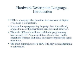
HDL (contd.) • As explained in your text: • The principal feature of a hardware description language is that it contains the capability to describe the function of a piece of hardware independently of the implementation. • The great advance with modern HDLs was the recognition that a single language could be used to describe the function of the design and also to describe the implementation. • This allows the entire design process to take place in a single language, and thus a single representation of the design.
Verilog • The Verilog Hardware Description Language, usually just called Verilog, was designed and first implemented by Phil Moorby at Gateway Design Automation in 1984 and 1985. • Verilog simulators are available for most computers at a variety of prices, and which have a variety of performance characteristics and features. • Verilog is more heavily used than ever, and it is growing faster than any other hardware description language. • It has truly become the standard hardware description language.
Verilog • A Verilog model is composed of modules. A module is the basic unit of the model, and it may be composed of instances of other modules. • A module which is composed of other module instances is called a parent module, and the instances are called child modules. system comp2 comp1 sub3
Verilog Design Concept System instantiates comp1,comp2 comp2 instantiates sub3 System comp1 comp2 sub3
Primitives • Primitives are pre-defined module types. They can be instantiated just like any other module type. • The Verilog primitives are sometimes called gates, because for the most part, they are simple logical primitives. • 1-output and,nand or,nor • 1-input buf,not Etc.
Register • Registers are storage elements. Values are stored in registers in procedural assignment statements. • Typical register declarations would be: reg r1, r2; reg [31:0] bus32; integer i; real fx1, fx2; • Register can take 0, 1, x (unknown) and z (high impedence)
Register Types • There are four types of registers: • Reg This is the generic register data type. A reg declaration can specify registers which are 1 bit wide to 1 million bits wide. A register declared as a reg is always unsigned. • Integer Integers are 32 bit signed values. Arithmetic done on integers is 2's complement. • Time Registers declared with the time keyword are 64-bit unsigned integers. • Real (and Realtime) Real registers are 64-bit IEEE floating point. Not all operators can be used with real operands. Real and realtime are synonymous.
Example • Primitives are instantiated in a module like any other module instance. For example, the module represented by this diagram would be instantiated: module test; wire n1, n2; reg ain, bin; and and_prim(n1, ain, bin); not not_prim(n2, n1); endmodule ain n2 n1 bin
Assign • Continuous assignments are sometimes known as data flow statements because they describe how data moves from one place, either a net or register, to another. They are usually thought of as representing combinational logic. • Example: assign w1 = w2 & w3;
Lets get the Verilog module for this circuit http://www.doulos.com/knowhow/verilog_designers_guide/wire_assignments/
Solutions using “assign” and “wire” module AOI (input A, B, C, D, output F); /* start of a block comment wire F; wire AB, CD, O; assign AB = A & B; assign CD = C & D; assign O = AB | CD; assign F = ~O; end of a block comment */ // Equivalent... wire AB = A & B; wire CD = C & D; wire O = AB | CD; wire F = ~O; endmodule // end of Verilog code
Module abc in vabc module vabc (d, s); input [1:0] s; output [3:0] d; abc a1 (d[3], d[2], d[1], d[0], s[1], s[0]); endmodule
Module Definition + Gate Level Diagram module abc (a, b, c, d, s1, s0); input s1, s0; output a, b, c,d; not (s1_, s1), (s0_, s0); and (a, s1_, s0_); and (b, s1_, s0); and (c, s1, s0_); and (d, s1, s0); endmodule
Verilog Module Example module shift (shiftOut, dataIn, shiftCount); parameter width = 4; output [width-1:0] shiftOut; input [width-1:0] dataIn; input [31:0] shiftCount; assign shiftOut = dataIn << shiftCount; endmodule This module can now be used for shifters of various sizes, simply by changing the width parameter. Parameters can be changed per instance. shift sh1 (shiftedVal, inVal, 7); //instantiation of shift module defparam sh1.width = 16; // parameter redefinition
Net component (connectors) • Nets are the things that connect model components together. They are usually thought of as wires in a circuit. Nets are declared in statements like this: • net_type [range] [delay3] list_of_net_identifiers ; • or • net_type [drive_strength] [range] [delay3]list_of_net_decl_assignments ; • Example: wire w1, w2; tri [31:0] bus32; wire wire_number_5 = wire_number_2 & wire_number_3; & here represents AND operation (AND gate)
Lets examine a full-adder • What is a half-adder? A+B {S, Cout} • What is a full-adder? A+B+Cin {S, Cout} • Determine the functions for sum and carry (S, Cout) from (A, B inputs and Cin) • S ==? • Cout =? • We will implement a 1-bit Adder module, build a 4-bit module out of it, then we will add a tester and a main module. • Adder