Verilog Hardware Description Language
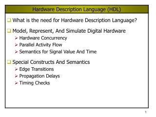
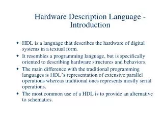
Verilog Hardware Description Language. Introduction. Verilog is a HARDWARE DESCRIPTION LANGUAGE (HDL) A hardware description language is a language or means used to describe or model a digital system: a network switch, a microprocessor a memory or a simple flip-flop. .


Verilog Hardware Description Language
E N D
Presentation Transcript
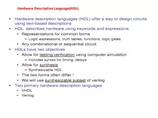
Introduction Verilog is a HARDWARE DESCRIPTION LANGUAGE (HDL) A hardware description language is a language or means used to describe or model a digital system: • a network switch, • a microprocessor • a memory • or a simple flip-flop. It is design representation of digital hardware describes to design software. It is a C like programming language
Hardware Description A digital circuit is defined as a module, like the function in C. module device_identifier ( I/O list ); declaration of I/O; declaration of internal wire connections; circuit description in either structural model or behavioral model endmodule module gate1 (x1, x2, f ); input x1, x2 ; output f ; nand g1 (f, x1, x2); assign f = ~ (x1 & x2); endmodule
Structural Model / Gate Level Model Circuit described in structural model is to define the circuit composes of: • What type of devices / logic gates • How they are connected In gate level model, all common logic gates are supported. Specified by: gate_type identifier (output, inputs); not, and, nand, or, nor, xor
Structural Model To use a predefined component, in Verilog, it is like functional call in C. • what component is being called • how it is connected to ( I/O lists, and its order ) module johnson_counter( clk, q0, q1, q2, q3 ) ; input clk ; output q0, q1, q2, q3 ; wireqb0, qb1, qb2, qb3 ; dff d0 ( clk , qb3 , q0 , qb0) ; dff d1 ( clk , q0 , q1 , qb1) ; dff d2 ( clk , q1 , q2 , qb2) ; dff d3 ( clk , q2 , q3 , qb3) ; endmodule /* D flip flop is a predefined component */ module dff(clk, D, Q, Qb); inputclk, D; output Q, Qb; always@(posedgeclk) Q <= D; Qb <= ~D; endmodule Johnson Counter
Behavioral Model Circuit described in behavioral model is to define the circuit by: • the logic functionality Specified by: assign output = logic function (inputs);