Download
1 / 52
540 likes | 729 Vues
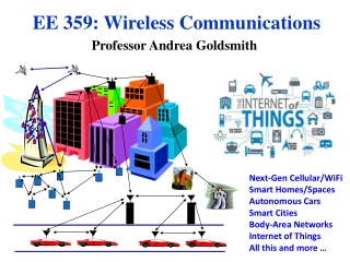
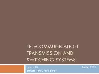
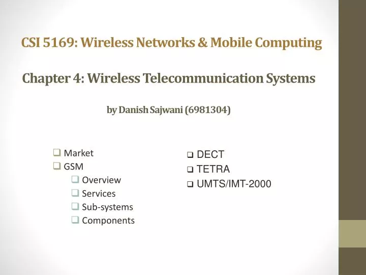
CSI 5169: Wireless Networks & Mobile Computing. Chapter 4: Wireless Telecommunication Systems by Danish Sajwani (6981304). DECT TETRA UMTS/IMT-2000. Market GSM Overview Services Sub-systems Components. Mobile phone subscribers worldwide. 1600. 1400. 1200. GSM total.

E N D
CSI 5169: Wireless Networks & Mobile Computing Chapter 4: Wireless Telecommunication Systemsby Danish Sajwani (6981304) • DECT • TETRA • UMTS/IMT-2000 Market GSM Overview Services Sub-systems Components
Mobile phone subscribers worldwide 1600 1400 1200 GSM total 1000 TDMA total CDMA total Subscribers [million] PDC total 800 Analogue total W-CDMA 600 Total wireless Prediction (1998) 400 200 0 1996 1997 1998 1999 2000 2001 2002 2003 2004 year
Development of mobile telecommunication systems CT0/1 FDMA AMPS CT2 NMT IMT-FT DECT IS-136 TDMA D-AMPS EDGE IMT-SC IS-136HS UWC-136 TDMA GSM GPRS PDC IMT-DS UTRA FDD / W-CDMA HSDPA IMT-TC UTRA TDD / TD-CDMA IMT-TC TD-SCDMA CDMA IS-95 cdmaOne IMT-MC cdma2000 1X EV-DO cdma2000 1X 1X EV-DV (3X) 2G 3G 1G 2.5G
Performance characteristics of GSM - Global System for Mobile Communication (wrt. analog sys.) • Communication • mobile, wireless communication; support for voice and data services • Total mobility • international access, chip-card enables use of access points of different providers • Worldwide connectivity • one number, the network handles localization • High capacity • better frequency efficiency, smaller cells, more customers per cell • High transmission quality • high audio quality and reliability for wireless, uninterrupted phone calls at higher speeds (e.g., from cars, trains) • Security functions • access control, authentication via chip-card and PIN
Disadvantages of GSM • There is no perfect system!! • no end-to-end encryption of user data • no full ISDN bandwidth of 64 kbit/s to the user, no transparent B-channel • reduced concentration while driving • electromagnetic radiation • abuse of private data possible • roaming profiles accessible • high complexity of the system • several incompatibilities within the GSM standards
GSM: Mobile Services • GSM offers • several types of connections • voice connections, data connections, short message service • multi-service options (combination of basic services) • Three service domains • Bearer Services • Telematic Services • Supplementary Services bearer services MS GSM-PLMN transit network (PSTN, ISDN) source/ destination network TE MT TE R, S Um (U, S, R) tele services
Bearer Services • Telecommunication services to transfer data between access points • Transparent bearer services only use the functions of the physical layer (layer 1) to transmit data • Non-transparent bearer services use protocols of layers two and three to implement error correction and flow control • Different data rates for voice and data (original standard) • data service (circuit switched) • synchronous: 2.4, 4.8 or 9.6 kbit/s • asynchronous: 300 - 1200 bit/s • data service (packet switched) • synchronous: 2.4, 4.8 or 9.6 kbit/s • asynchronous: 300 - 9600 bit/s • Today: data rates of approx. 50 kbit/s possible.
Tele Services I • Telecommunication services that enable voice communication via mobile phones • All these basic services have to obey cellular functions, security measurements etc. • Offered services • mobile telephonyprimary goal of GSM was to enable mobile telephony offering the traditional bandwidth of 3.1 kHz • Emergency numbercommon number throughout Europe (112); mandatory for all service providers; free of charge; connection with the highest priority (preemption of other connections possible) • Multinumberingseveral ISDN phone numbers per user possible
Tele Services II • Additional services • Non-Voice-Teleservices • group 3 fax • voice mailbox (implemented in the fixed network supporting the mobile terminals) • electronic mail (MHS, Message Handling System, implemented in the fixed network) • Short Message Service (SMS)alphanumeric data transmission to/from the mobile terminal (160 characters) using the signaling channel, thus allowing simultaneous use of basic services and SMS(almost ignored in the beginning now the most successful add-on!)
Architecture of the GSM system • GSM is a PLMN (Public Land Mobile Network) • several providers setup mobile networks following the GSM standard within each country • components • MS (mobile station) • BS (base station) • MSC (mobile switching center) • VLR (Visitor location register) • subsystems • RSS (radio subsystem): covers all radio aspects • NSS (network and switching subsystem): call forwarding, handover, switching • OSS (operation subsystem): management of the network
GSM: overview OMC, EIR, AUC fixed network HLR GMSC NSS with OSS VLR MSC VLR MSC BSC BSC RSS
GSM: elements and interfaces radio cell BSS MS MS Um radio cell MS RSS BTS BTS Abis BSC BSC A MSC MSC NSS VLR VLR signaling HLR ISDN, PSTN GMSC PDN IWF O OSS EIR AUC OMC
System architecture: network and switching subsystem networksubsystem fixed partnernetworks • Components • MSC (Mobile Services Switching Center): • IWF (Interworking Functions) • ISDN (Integrated Services Digital Network) • PSTN (Public Switched Telephone Network) • PSPDN (Packet Switched Public Data Net.) • CSPDN (Circuit Switched Public Data Net.) • Databases • HLR (Home Location Register) • VLR (Visitor Location Register) • EIR (Equipment Identity Register) ISDNPSTN MSC EIR SS7 HLR VLR ISDNPSTN MSC IWF PSPDNCSPDN
cell GSM: cellular network segmentation of the area into cells possible radio coverage of the cell • use of several carrier frequencies • not the same frequency in adjoining cells • cell sizes vary from some 100 m up to 35 km depending on user density, geography, transceiver power etc. • hexagonal shape of cells is idealized (cells overlap, shapes depend on geography) • if a mobile user changes cells handover of the connection to the neighbor cell idealized shape of the cell
GSM: cellular network • The area covered by a cell, i.e., one hexagon, may be determined using equation: • For instance, if r is 1.5 km, then the area covered by a hexagon cell is 5.8 km2 • A cluster of 32 such cells covers • 32 cells * 5.8 km2/cell = 187.1 km2
GSM: cellular network • The minimum distance between cells using the same frequency is: • If n is the number of cells in a cluster. • The variable n is termed the Reuse Factor • For example: • AMPS has 392 frequencies • With a reuse factor of four, 392/4 = 98 frequencies may be assignedto each cell. • If we assume that each frequency can support one call, then with a reuse factor four a 32 cell system may support up to:
GSM frequency bands • Additionally: GSM 400 (also named GSM 450 or GSM 480 at 450-458/460-468 or 479-486/489-496 MHz • Please note: frequency ranges may vary depending on the country! • Channels at the lower/upper edge of a frequency band are typically not used
Mobile Services Switching Center • The MSC (mobile switching center) plays a central role in GSM • switching functions • additional functions for mobility support • management of network resources • interworking functions via Gateway MSC (GMSC) • integration of several databases • Functions of a MSC • specific functions for paging and call forwarding • termination of SS7 (signaling system no. 7) • mobility specific signaling • location registration and forwarding of location information • provision of new services (fax, data calls) • support of short message service (SMS) • generation and forwarding of accounting and billing information
higher GSM frame structures 5 7 8 1 2 4 6 3 4.615 ms 546.5 µs 577 µs GSM - TDMA/FDMA 935-960 MHz 124 channels (200 kHz) downlink frequency 890-915 MHz 124 channels (200 kHz) uplink time GSM TDMA frame Prof. Dr.-Ing. Jochen Schiller, http://www.jochenschiller.de/ MC SS05 4.19 GSM time-slot (normal burst) guard space guard space S user data tail tail user data S Training 1 3 1 57 bits 3 bits 57 bits 26 bits
GSM - TDMA/FDMA • The first and last three bits of a normal burst (tail) are all set to 0 and can be used to enhance the receiver performance. • The training sequence in the middle of a slot is used to adapt the parameters of the receiver to the current path propagationcharacteristics and to select the strongest signal in case of multi-path propagation. • A flag S indicates whether the data field contains user or network control data.
PSTN Mobile Terminated Call 4 • 1: calling a GSM subscriber • 2: forwarding call to GMSC • 3: signal call setup to HLR • 4, 5: request MSRN from VLR • 6: forward responsible MSC to GMSC • 7: forward call to • current MSC • 8, 9: get current status of MS • 10, 11: paging of MS • 12, 13: MS answers • 14, 15: security checks • 16, 17: set up connection HLR VLR 5 8 9 3 6 14 15 7 calling station GMSC MSC 1 2 10 13 10 10 16 BSS BSS BSS 11 11 11 11 12 17 MS
PSTN Mobile Originated Call • 1, 2: connection request • 3, 4: security check • 5-8: check resources (free circuit) • 9-10: set up call VLR 3 4 6 5 GMSC MSC 7 8 2 9 1 MS BSS 10
Security in GSM • Security services • access control/authentication • user SIM (Subscriber Identity Module): secret PIN (personal identification number) • SIM network: challenge response method • confidentiality • voice and signaling encrypted on the wireless link (after successful authentication) • anonymity • temporary identity TMSI (Temporary Mobile Subscriber Identity) • newly assigned at each new location update (LUP) • encrypted transmission • 3 algorithms specified in GSM • A3 for authentication (“secret”, open interface) • A5 for encryption (standardized) • A8 for key generation (“secret”, open interface) “secret”: • A3 and A8 available via the Internet • network providers can use stronger mechanisms
GSM - authentication SIM mobile network RAND Ki RAND RAND Ki 128 bit 128 bit 128 bit 128 bit AC A3 A3 SIM SRES* 32 bit SRES 32 bit SRES SRES* =? SRES MSC SRES 32 bit Ki: individual subscriber authentication key SRES: signed response
GSM - key generation and encryption MS with SIM mobile network (BTS) RAND Ki RAND RAND Ki AC SIM 128 bit 128 bit 128 bit 128 bit A8 A8 cipher key Kc 64 bit Kc 64 bit SRES data encrypteddata data BSS MS A5 A5
Data services in GSM I • Data transmission standardized with only 9.6 kbit/s • advanced coding allows 14,4 kbit/s • not enough for Internet and multimedia applications • HSCSD (High-Speed Circuit Switched Data) • mainly software update • bundling of several time-slots to get higher AIUR (Air Interface User Rate)(e.g., 57.6 kbit/s using 4 slots, 14.4 each) • advantage: ready to use, constant quality, simple • disadvantage: channels blocked for voice transmission
Data services in GSM II • GPRS (General Packet Radio Service) • packet switching • using free slots only if data packets ready to send (e.g., 50 kbit/s using 4 slots temporarily) • standardization 1998, introduction 2001 • advantage: one step towards UMTS, more flexible • disadvantage: more investment needed (new hardware) • GPRS network elements • GSN (GPRS Support Nodes): GGSN and SGSN • GGSN (Gateway GSN) • interworking unit between GPRS and PDN (Packet Data Network) • SGSN (Serving GSN) • supports the MS (location, billing, security) • GR (GPRS Register) • user addresses
SGSN Gn PDN MS BSS SGSN GGSN Um Gb Gn Gi HLR/ GR MSC VLR EIR GPRS architecture and interfaces • Gateway GPRS Support Node • contains routing information for GPRS users, • Performs address conversion, and • tunnels data to a user via encapsulation • Serving GPRS support node • requests user addresses from the GPRS register (GR), • keeps track of the individual MSs’ location, • is responsible for collecting billing information (e.g., counting bytes), and • performs several security functions such as access control.
DECT • DECT (Digital European Cordless Telephone) standardized by ETSI (ETS 300.175-x) for cordless telephones • standard describes air interface between base-station and mobile phone • DECT has been renamed for international marketing reasons into „Digital Enhanced Cordless Telecommunication“ • Characteristics • frequency: 1880-1990 MHz • channels: 120 full duplex • duplex mechanism: TDD (Time Division Duplex) with 10 ms frame length • multplexing scheme: FDMA with 10 carrier frequencies, TDMA with 2x 12 slots • modulation: digital, Gaußian Minimum Shift Key (GMSK) • power: 10 mW average (max. 250 mW) • range: approx. 50 m in buildings, 300 m open space
DECT system architecture reference model D4 D3 VDB D2 PA PT FT local network HDB PA PT D1 global network FT local network
TETRA - Terrestrial Trunked Radio • Trunked radio systems • many different radio carriers • assign single carrier for a short period to one user/group of users • For example, taxi service, fleet management, rescue teams • interfaces to public networks, voice and data services • very reliable, fast call setup, local operation • System architecture very similar to GSM but no handover • TETRA - ETSI standard • formerly: Trans European Trunked Radio • point-to-point and point-to-multipoint • encryption (end-to-end, air interface), authentication of devices, users and networks • group call, broadcast, sub-second group-call setup • ad-hoc (“direct mode”), relay and infrastructure networks • call queuing with pre-emptive priorities
TETRA – Contracts by Sector (percentage) Used in over 70 countries, more than 20 device manufacturers
UMTS and IMT-2000 • Proposals for IMT-2000 (International Mobile Telecommunications) • UWC-136, cdma2000, WP-CDMA • UMTS (Universal Mobile Telecommunications System) from ETSI • UMTS • UTRA (was: UMTS, now: Universal Terrestrial Radio Access) • Difference is that specific proposal for the radio interface RTT is • Enhancements of GSM • EDGE (Enhanced Data rates for GSM Evolution): • Middle man betwween UMTS and GSM • CAMEL (Customized Application for Mobile Enhanced Logic) • CAMEL supports VHE (virtual Home Environment) • Fits into GMM (Global Multimedia Mobility) initiative from ETSI • GMM provides an architecture to integrate mobile and fixed terminals
UMTS architecture • UTRAN (UTRA Network) • Cell level mobility • Radio Network Subsystem (RNS) • Encapsulation of all radio specific tasks • UE (User Equipment) • comparable to the Um interface in GSM • CN (Core Network) • Inter system handover • Location management if there is no dedicated connection between UE and UTRAN Uu Iu UE UTRAN CN
Spreading and scrambling of user data • The duplex mechanisms are already well known from GSM (FDD) and DECT. However, the direct sequence (DS) CDMA used in UMTS is new • Different user data rates supported via different spreading factors • higher data rate: less chips per bit and vice versa • User separation via unique, quasi orthogonal scrambling codes • users are not separated via orthogonal spreading codes • much simpler management of codes: each station can use the same orthogonal spreading codes • precise synchronization not necessary as the scrambling codes stay quasi-orthogonal data1 data2 data3 data4 data5 spr. code1 spr. code2 spr. code3 spr. code1 spr. code4 scrambling code1 scrambling code2 sender1 sender2
Orthogonal variable spreading factor (OVSF) Codes Two codes are orthogonal as long as one code is never a part of the other code Valid Code: (1,–1), (1,1,–1,–1), (1,1,1,1,1,1,1,1), (1,1,1,1,–1,–1,–1,–1,1,1,1,1,–1,–1,–1,–1), (1,1,1,1,–1,–1,–1,–1,–1,–1,–1,–1,1,1,1,1)
Direct Sequence Spread Spectrum (DSSS) • 110 001 110 110 Received Bits • 110 Barker’s Code
UTRAN architecture RNS RNC: Radio Network Controller RNS: Radio Network Subsystem UE1 Iub Node B Iu RNC CN UE2 Node B Node B UTRAN comprises several RNSs Node B can support FDD or TDD or both RNC is responsible for handover decisions requiring signalingto the UE Cell offers FDD or TDD UE3 Iur Node B Iub Node B RNC Node B Node B RNS
UTRAN functions • Admission control • Congestion control • System information broadcasting • Radio channel encryption • Handover • SRNS moving • Radio network configuration • Channel quality measurements • Macro diversity • Radio carrier control • Radio resource control • Data transmission over the radio interface • Outer loop power control (FDD and TDD) • Channel coding • Access control
Wireless Sensor Networks • A wireless sensor network consists of spatially distributed autonomous sensors • They monitor physical or environmental conditions, such as temperature, sound, pressure, etc. • They cooperatively pass their data through the network to a main location
Energy Efficiency in Wireless Sensor Networks • Node Disconnection • Disconnection detected by an acknowledgement mechanism: • Receiving node sends ACK to sender • When an ACK is missing, the sender will keep awake until another node is able to receive the frame • A Low Energy Consumption MAC Protocol for WSN:
Energy Efficiency in Wireless Sensor Networks • Node Connection • First Round: • The node detects several parameters of the gossiping between nodes (Round period length, last receiving slot, leaderID • During the slot of the last node it announces that it is willing to join the network • Second Round: • A Low Energy Consumption MAC Protocol for WSN:
Some current enhancements • GSM • EMS/MMS • EMS: 760 characters possible by chaining SMS, animated icons, ring tones, was soon replaced by MMS (or simply skipped) • MMS: transmission of images, video clips, audio • see WAP 2.0 / chapter 10 • EDGE (Enhanced Data Rates for Global [was: GSM] Evolution) • 8-PSK instead of GMSK, up to 384 kbit/s • new modulation and coding schemes for GPRS EGPRS • MCS-1 to MCS-4 uses GMSK at rates 8.8/11.2/14.8/17.6 kbit/s • MCS-5 to MCS-9 uses 8-PSK at rates 22.4/29.6/44.8/54.4/59.2 kbit/s • UMTS • HSDPA (High-Speed Downlink Packet Access) • initially up to 10 Mbit/s for the downlink, later on 20 Mbit/s using MIMO- (Multiple Input Multiple Output-) antennas • uses 16-QAM instead of QPSK
References • - http://www.mob1le.com/acronyms.html • - Textbook: Wireless Mobile Communications, Networks & Security by Michel Barbeau, PhD • - A Low Energy Consumption MAC Protocol for WSN from IEEE ICC 2012 - Ad-hoc and Sensor Networking Symposium Thibault Bernard and Hac`ene Fouchal CReSTIC Lab Universit´e de Reims Champagne-Ardenne, France • - Mobile Communication 2nd Edition by Jochen Schiller
Question 1 • The Direct Sequence Spread Spectrum (DSSS) spreading code is used with the following received bits: 1 1 1 0 0 0 0 0 0 0 0 1 • Calculate the auto-correlation as a function of the received bit position and sketch its graph. Explain briefly why is auto-correlation is used? • Note: Barker’s Code 1110 • Answer: • Auto-correlation : 4 2 0 -2 -2 -2 -2 -2 -4 • Auto-correlation value 4 marks the beginning of binary value zero. • Auto-correlation value -4 marks the beginning of binary value one.
Question 2 • Using the following diagram write 4 different OVSF Codes that a sender can send simultaneously. Briefly explain how sending the data using different SFs can help in communication. Answer: (1,–1), (1,1,–1,–1), (1,1,1,1,1,1,1,1), (1,1,1,1,–1,–1,–1,–1,1,1,1,1,–1,–1,–1,–1) Different spreading factors directly translates into the support of different data rates. This means that UMTS can only support a single data stream with SF=1 as then no other code may be used. Using the example combination above, a stream with half the maximum data rate, one with a fourth, one with an eighth, and two with a sixteenth are supported at the same time.
Question 3 • Describe briefly how the energy consumption is minimized by using “Low Energy Consumption MAC Protocol for wireless sensor networks”. Using the diagrams below explain briefly the node connection and disconnection procedure for. Explain what happens during each round. Prof. Dr.-Ing. Jochen Schiller, http://www.jochenschiller.de/ MC SS05 4.49
Answer 3 Node Connection: When a node would like to join the network, it will spend three rounds before being inserted. In the first round, the new node has to keep listening. It announces that it is willing to join the network during the slot of the last node. Node Disconnection: The disconnection will be detected by acknowledgement mechanism: a node which receives the frame, will send an ack to the sender node. When an ack is missing, the sender will keep awake until another node is able to receive the frame. In the first round, all nodes are running. In the second round, a node is disconnected and in the meantime, its previous node keeps waiting for an acknowledgment which will come from the next node. In the next round, all nodes shift their slot since they have been informed about the node disconnection. This method ensures to save high amount of energy because each node spends more time in the sleeping mode than usual methods.