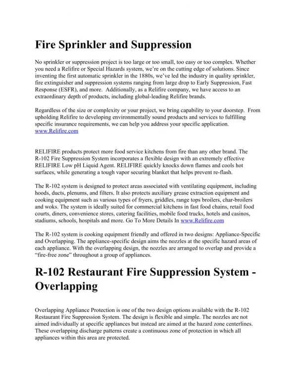
Simulation Methods for Fire Suppression Process inside Engine Core and APU Compartments
Simulation Methods for Fire Suppression Process inside Engine Core and APU Compartments. The Fourth Triennial International Aircraft Fire and Cabin Safety Research Conference Lisbon Conference Center, Portugal November 15-18, 2004. Jaesoo Lee. Boeing Commercial Airplanes Group

Simulation Methods for Fire Suppression Process inside Engine Core and APU Compartments
E N D
Presentation Transcript
Simulation Methods for Fire Suppression Process inside Engine Core and APU Compartments The Fourth Triennial International Aircraft Fire and Cabin Safety Research Conference Lisbon Conference Center, Portugal November 15-18, 2004 Jaesoo Lee Boeing Commercial Airplanes Group Seattle, Washington, 98124-2207, USA
Acknowledgment • FAA Tech Center: • D. Ingerson: Nacelle Fire Simulator Test Data • Boeing: • C. Roseburg: Thermodynamic Properties of Agents • A. Nazir: Hflowx Modification • D. Lackas, J. Petkus: Certification Test Data • M. Dunn: Engine Cooling Airflow Data • D. Dummeyer: APU FireX Test Data • M. Grueneis, R. Moody, B. Hsiao: Mesh Generation
Outline • Introduction / Background • Engine Fire Suppression Process • Simulation Methods: • FireX System • Agent Concentration Distribution • Example Applications: • FAA Nacelle Fire Simulator • APU Compartment • Engine Core Compartment • Conclusions • Future Activities
Engine Fire / Overheat Detection and Fire Extinguishing Aural / Visual Warnings Engine Fire Switch Thermal Sensors fireX agent fireX agent J. Lee, 11-17-04
Environmental and Physical Properties (Halon 1301 and Alternate FireX Agents) Halon HFC CF3I BTP 1301 -125 Properties Chemical Formula CF3Br CF3CHF2 CF3ICH2CBrCF3 Ozone Depletion Potential 16 0 0.0002 0.0037 Molecular Weight 148.9 120.0 196.9 174.9 Global Warming Potential 5600 2800 5 400 Critical Temperature, ºF 152.6 151.3 251 - Atmospheric Lifetime, years 65 33 0.0137 0.011 Liquid Density at 77 ºF, lb/ft3 96.01 74.3 131.4 102.9 Boiling Point, ºF -72 -55 -9 34 Heat of Vaporization, Btu/lb 35.5 70.7 48.1 - Vapor Pressure at 77 ºF, psia 234.8 200.4 63.710.9
Certification Requirement (Engines and APUs) • If Halon 1301 (CF3Br) is used as the fire extinguishing agent, the minimum agent concentration is 6 % by volume for a minimum of 0.5 seconds for all 12 concentration probe locations, simultaneously (FAA AC 20-100). Range of Concentration Histories max. conc. history %V/V 10 9 7 6 8 12 4 min. conc. history 6.0 3 11 5 2 1 Probe Locations inside APU Compartment ½ sec Time Injection Nozzle
Technology Status and Need • No Analysis Tool to Simulate the Entire Fire Suppression Process • for Engines and APUs. • FireX System can be Over-Designed (Heavy, Excess Discharge • of Agent to Environment) or Under-Designed. • Installation of Injection Nozzles: • Many Ground Tests to meet FAA Requirements. • Time-Consuming and Costly. • Need an Analytical Tool for Performance Design of FireX Systems: • Engine Nacelles / APUs of Commercial, Military Airplanes, Helicopters. • Reduces Cost of Design / Certification by ~50 Percent. • Technology Ready for Halon Replacement.
Simulation of Fire Extinguishing Process FireX Agent Storage Storage Bottle Liquid- / Gas-Phase FireX Agent / N2 Distribution Pipe Challenges: • Complex Geometries • Uncertainties in Airflow Sources • Complicated Flow Physics: • Two-Phase Agent Jet Flow • Droplet Formation / Break-up • Droplet Interaction with Solid Surfaces • Two-Phase CFD Problems • Coupled Transport Phenomena • Long Analysis Cycle Time Injection Injection Nozzles Nozzles Air/Agent Mixture Gas Vented air air Engine Core Compartment Compartment Non-Pressurized
Elements of the Simulation Process Post-Processing for Concentration Histories CFD Analysis for Concentration Propagation FireX System Analysis Initial Vented Airflow Distribution Engine Core Compartment Geometry CFD Mesh Generation
Unsteady Analysis of Agent Injection Process Agent Agent Storage Storage Bottle Bottle Agent Mass, Bottle (P, T, Vol), Distribution Pipes, Nozzle Size Distribution Pipe Multiple Injection Nozzles Hflowx Unsteady BCs at Injection Nozzles ŵ (t)liquid ŵ (t)vapor P (t)mixture T (t)mixture
Validation Analysis of Hflowx • Agent Types: • ICHEM = 1 (Halon 1301) • = 2 (HFC-125) • = 3 (CF3I) STORAGE BOTTLE FLOW SPLIT • 55/8” TUBE NOZZLES • Halon Mass = 5.2 lbm • Bottle Volume = 219 In3 • Charge Pressure = 720 psig • Test Temperature = 100 ºF • 9/32”ID ORIFICE
Predicted Agent Discharge Characteristics FireX System Conditions Agent Mass: 22 lbm Bottle Volume: 800 In3 Charge Press.: 825 psia Test Temp.: 10 F Pipe Diameter: 0.75 In Pipe Length: 80 Ft Two-Phase Vapor / Liquid Mixture Jet Liquid-Phase Agents Vapor-Phase Agents
CFD Modeling of Agent Injection / Conc. Propagation Process Liquid Agent Droplets Air / Agent Gas Mixture Lagrangian Description Eulerian Description • • • • • • Mass Transport Eq. Mass Transport Eq. Mass Transport Eq. Mass Continuity Eq. Mass Continuity Eq. Mass Continuity Eq. 2 2 - - Way Way (Evaporation) (Evaporation) (Evaporation) • • • Momentum Eqs. Momentum Eqs. Momentum Eqs. Coupling Coupling • • • Momentum Transport Eqs. Momentum Transport Eqs. Momentum Transport Eqs. • • • Energy Eq. Energy Eq. Energy Eq. (Trajectories) (Trajectories) (Trajectories) • • • Species Transport Eq. Species Conservation Eq. Species Conservation Eq. • • • Energy Transport Eq. Energy Transport Eq. Energy Transport Eq. • • • (Heat Transfer) (Heat Transfer) (Heat Transfer) Turbulence Model Eqs. Turbulence Model Eqs. Turbulence Model Eqs. Injector nozzle
CFD Input Data / Solution Control • Unsteady Vented Airflows: • Pre-Cooler Air, Bleed Air • Turbine Cooling Air, Leaks • Unsteady Agent Injection at Nozzles: • Vapor-Phase Flow • Liquid-Phase Flow • Droplet Size • Two-Phase Flow Velocities • Droplet Break-up Model. • Droplet-Solid Surface Interaction. • Non-Slip / Thermal BCs on Surfaces. • Thermodynamic Properties of Agent. Solution Controls Eff. Conditions Time-Marching 2nd–Order Implicit Iterations per time-step 30 ~60 Pressure-Velocity Coupling SIMPLE Discretization Schemes 2nd –Order Upwind Calculation Precision Double-Precision Under-Relaxation Scheme All Transport Eqs. Buoyancy Effect yes Variable Time Steps Agent Injection Concentration Propagation
Volumetric Concentration av = fh / [fh + (1 - fh) (Mh/Ma)] where, fh = Predicted Mass Fraction of Agent Mh = Mol. Weight of Agent Vapor Ma = Mol. Weight of Air av = Volumetric Concentration v, %V/V time, sec
Validation Application - Case 1 (FAA Nacelle Fire Simulator) Axial View Vertical Center Plane Flanges Fuel Nozzles Engine Core Exhaust gas Injection Nozzles and Orifices airflow Exhaust Gas Pipe Pool Fire Test Pan
Halon 1301 Concentration Histories 12 Probe Locations 4 Probes (12, 3, 6, 9 o’clocks) Measured 4 Probes (4:30, 7:30, 12, 6 o’clocks) 4 Probes (12, 3, 6, 9 o’clocks) • Vented Airflow: • Unsteady Airflow Rate: (2.2 lbm/sec @ steady-state) • Temperature: 100 °F • FireX Condition: • Halon 1301 Mass: 5.2 lbm • Bottle Volume: 219 in3 • Bottle Charge: 812 psi, 100 °F • Discharge Temp.: 100 °F Predicted
Validation Application - Case 2 (APU Compartment) Initial Airflow Pattern Surface Mesh Side View Top View t = 0.30 sec after injection
Halon 1301Concentration Histories Measured 10 9 7 6 8 12 4 3 11 5 2 1 Probe Locations Predicted • Agent Injection: • Halon Mass: 14 lbm • Charge Pressure: 600 psi • Bottle Vol.: 536 In3 • Vent Air: • Initial avg. Air Temp.: 125 ºF • Transient Vented airflow
Validation Application - Case 3 (Engine Core Compartment) t = 0.13 s Surface Mesh Airflow Streamlines t = 7.10 s • Halon 1301 Flow: • Mass (CBrF3) = 22 lbm • Bottle Volume = 800 in3 • P (Charge) = 825 psia • Vented Airflow: • Flow Rate = 12.84 lbm/sec t = 3.70 s
Analysis Types / Cycle Times Analysis Types Computer Platform Analysis Time♣ Remarks SGI Octane2 400 MHz < 1 Min. FireX System ORIGIN 3800 (4 cpus) ~0.5 Day 0.32 Mcells Steady- State Initial Airflow Distribution ORIGIN 3800 (6 cpus) ~1 Wk 1 Injection Nozzle Unsteady Agent Injection / Concentration Distribution ♣ : CPU time depends on: Total simulation time; Size of CFD mesh; No. of injection nozzles; No. of droplet sizes; No. of droplet starting locations per nozzle; No. of computer processors; Convergence criteria, etc.
Key Factors for Improved Simulations • Analysis Domain based on Fire Suppression Process. • Advanced Flow Physics Models: • - Two-Phase Agent Jet Flow • - Droplet Interaction with Solid Surfaces • Accurate Airflow / Agent Jet Flow Boundary Conditions. • Refined CFD Mesh including Details of Important • Geometry. • Accurate Property Correlations of Agents.
Conclusions • Simulation Methods for Fire Suppression Process inside • Aircraft Propulsion Systems have been Developed. • The Capabilities of the Methods have been Demonstrated • by Simulating the FireX Tests of Engines and APUs. • Predicted Concentration Histories are well Correlated • with Measured Data. • The Simulation Methods need to be Improved for More • Accurate Prediction of Concentration Histories.
Future Activities • Continuous Improvement of • the Developed Methods to Enhance Applicability and Practicality. • Support the Design and Installation of FireX System • for Commercial, Military Airplanes, Helicopters, and for Halon Replacements. • Complement of the FAA Certification Tests. 7E7 Dreamliner