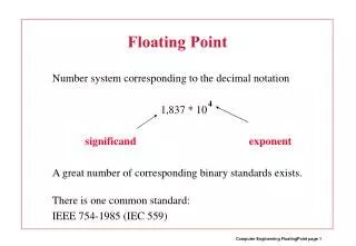
Floating-Gate Circuits
Floating-Gate Circuits. Prof. Paul Hasler. Floating-Gate MOS Circuits. Floating-Gate Translinear Circuits. (MITE Networks). I out = I 1 2 / I 2. Other Applications:Amplifiers, Filters, Log-Domain Filters, Sensor Interfaces. Developed by B. Minch, et. al.

Floating-Gate Circuits
E N D
Presentation Transcript
Floating-Gate Circuits Prof. Paul Hasler
Floating-Gate Translinear Circuits (MITE Networks) Iout = I12 / I2 Other Applications:Amplifiers, Filters, Log-Domain Filters, Sensor Interfaces Developed by B. Minch, et. al
Capacitor-Based Circuits Capacitor-Based Design Resistor-Based Design Resistors and Inductors define the circuit dynamics Capacitors and Inductors define the circuit dynamics Capacitors are the natural elements on silicon ICs
A Floating-Gate Technology for Digital CMOS Processes C1 V1 Cf • Creates a DC Measurement • of classic C-V curves C2 V2 C3 Vout V3 Vref V4 Gain = DVout/ DVin = - C1 / Cf C4 Single-Poly FG Circuits: Brought to you by Brad and Paul
Floating-Gate Multiplication V V 23 dd dd 22 V V nA) tun tun 21 V dibl 20 Output Current ( + - W = 0 W = 0 V V in in 19 W = -0.35 W = 0.35 W = -0.70 W = 0.70 18 + - I I out out W = -1.40 17 W = 1.40 I out -0.5 -0.4 -0.3 -0.2 -0.1 0 0.1 0.2 0.3 0.4 0.5 Differential input (V)
Dynamics Range in the AFGA AFGA Linear Range AFGA Noise Spectrum
V dd V V dd t p 3.8 V dd 3.7 M p 3.6 Increasing Smalle r Variable Capacitance C Increase 3.5 V 2 Capacitor out 3.4 3.3 V M t n 3.2 Smalle r Decreasin g Decreas e Capacitance 3.1 3 2.9 0 0.2 0.4 0.6 0.8 1 1.2 1.4 1.6 1.8 2 Tim e ( s) Floating-Gate Based Capacitor Sensor Circuit Pseudo-AFGA circuit AFGA circuit
AutoSOS Frequency Behavior AutoSOS Step Responses
C4 Pseudo-AFGA Tunneling Circuit Injection Circuit C4 (Capacitively Coupled Current Conveyors) AFGA Hasler, Kucic, and Minch, Midwest 99
10 V t p = 2. 56 1V V t = 0 .6 10 V V t = V t p = Gain 0. 5 8 9 V 2. 5 3 7 V 1 V t p = 2. 50 1V V t = 0 .5 44 V 0.2 1 2 3 4 5 10 10 10 10 10 Frequency (Hz) PAFGA Frequency Response