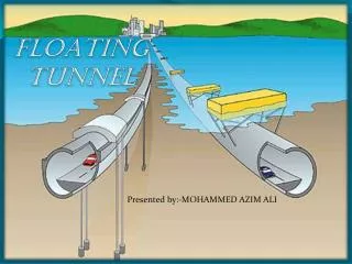
FLOATING TUNNEL
FLOATING TUNNEL. Presented by:-MOHAMMED AZIM ALI. CONTENTS . INTRODUCTION CONCEPT OF SUBMERGED FLOATING TUNNEL PRINCIPLE HOW IS IT CONSTRUCTED ? DESIGN PRESENT SCENARIO NEED FOR SUBMERGE FLOATING TUNNEL ESTIMATION CONCLUSION. INTRODUCTION.

FLOATING TUNNEL
E N D
Presentation Transcript
FLOATING TUNNEL Presented by:-MOHAMMED AZIM ALI
CONTENTS. • INTRODUCTION • CONCEPT OF SUBMERGED FLOATING TUNNEL • PRINCIPLE • HOW IS IT CONSTRUCTED ? • DESIGN • PRESENT SCENARIO • NEED FOR SUBMERGE FLOATING TUNNEL • ESTIMATION • CONCLUSION.
INTRODUCTION • Submerged floating tunnel is basically making a tunnel to float underwater which is balanced by its buoyancy, self weight and constraint forces resulted from cable system and thus submerged to a certain depth underwater. • It is basically tube like structure floating at some depth below water surface and fixed against excessive movements. The tube is designed to accommodate road and or rail traffic.
What is Submerged Floating Tunnel • A Submerged Tunnel is a tunnel that floats in water ,supported by its buoyancy (specifically by employ-ing the hydrostatic thrust) . • The tube is placed underwater ,deep enough to avoid water traffic and weather ,but not so deep that high water pressure needs to be dealt with, usually 20m-50m(60ft-150ft) is sufficient. • This allows submerged tunnel approaches to be shorter and approach gradient to be flatter.
ARCHIMEDES PRINCIPLE • Any object wholly or partially immersed in an fluid, is buoyed up by a force equal to the weight of the fluid displaced by the object. • This means if more surface area exposed to water surface more are the chances of floating it. • Ships, submarines, offshore oil rigs etc. work on this principle. • Research shows that the buoyancy to weight ratio for the tunnel to float should be less than one and between 0.5 to 0.8
How this is constructed • A trench is dredged in the bed of water channel. • DREDGING. Dredging technology has improved considerably in recent years and it is now possible to remove a wide variety of material underwater without adverse effects on the environment of waterway.
Step by step procedure • Construction of tunnel segments on dry dock. • Transporting the tunnel segments to their final places and placing them underwater. • Joining of different tunnel segments by using rubber gasket. • Anchoring the tunnel to the cables.
STEP ONE - PRECASTING • Huge tunnel sections are constructed on dry dock. • The procedure consists same as that of precast construction. • Dry dock is flooded and the panels are transported to their respective places. • Sinking of the panel is controlled by the use of ballast tank as in case of submarines.
STEP TWO- JOINTS • After the submersion of different panels in water they are connected with one another by using a rubber gasket. • Another procedure includes trapping of water between the joints and then removing it afterwards.
STEP THREE - FOUNDATIONS • The application consists same as that of in caisson foundation. • A hollow chamber is penetrated down the sea bed as shown which evacuates the water trapped inside it by a valve present on its top surface. • Such type of foundations are been used for the offshore oil rig plants.
STEP FOUR - ANCHORING OF CABLES • After the foundation work is completed the cables are anchored to the floating tunnel which will avoid its movement and will place it firmly in alignment. • This operation can be carried out by divers. • Finally the tunnel will be in position and ready to use.
MATERIAL USED: • As the tunnel is situated at a depth of 30m, it should be perfectly water tight and secondly it should resist the salty sea water and thirdly it should withstand against hydrostatic forces coming on it. • It is made of 4 layers. Outermost layer is constructed of aluminium to resist the salty sea water. Second and third layer is made of the foam to float the tunnel easily in water. Fourth layer is of concrete which gives strength to the tunnel.
PRESENT SCENARIO • A simple submerged tunnel have been used as a means of transport for about 100 years. • They are considered to built when the underneath ground surface is shallow and the tunnel can be placed directly on sea bed and can be covered by sand and backfill material so as to avoid their movement.
NEED FOR SUBMERGED FLOATING TUNNEL • A Submerge Floating Tunnel is considered when the depth of sea or ocean is too deep so that no tunnel or any solid body could sustain the pressure acting on it at such a deep level. • In that case the tunnel is lifted up such as about 30 to 100m deep from the sea surface where the water pressure is comparatively lower than what is at the bottom depth.
PARAMETERS OF A SUBMERGE FLOATING TUNNEL An Submerged Floating Tunnel basically consists of four parts • The tunnel structure which is made of different segments • The shore connection structure which connects it to shores. • The cable systems which are anchored to the waterbeds to balance net buoyancy. • The foundation structure which are constructed at waterbed to install cable system.
Advantages of Submerged Floating Tunnel • Allows construction of tunnel in extremely deep water. • Any type of cross sectional area can be provided since being prefabricated. • No obstruction to navigational routes as compared to conventional bridges since all of the tunnel being placed underwater. • Construction activities has less harmful effects on aquatic life.
No harmful environmental effects such as fog or storm since the whole structure is covered and is present inside the water. • Low energy consumption due to more gentle gradient. • Vehicular emission can be collected at one end of the tunnel thus reducing the air pollution. • Tremendous speed for trains could be obtained by creating a vacuum inside the tunnel since it will result in negligible air resistance.
TRANSATLANTIC TUNNEL • AIM- to join north America to west Europe via a submerged floating tunnel present in the Atlantic ocean. • Will require 54000 prefabricated tunnel segments. • Use of maglev trains for fast travel. • Maintaining perfect vacuum to avoid air resistance. • Could travel from New York to London within 54 minutes with a tremendous speed of 8000km/h.
CONCLUSION:- The submerged floating tunnel will set up new trends in transportation engineering The advances in technology that will reduce the time required for travelling. The transportation is more effective by hiding the traffic under water by which the beauty of landscape is maintained and valuable land is available for other purposes. Benefits can be obtained with respect to less energy consumption, air pollution and reduced noise emission. For wide and deep crossings the submerged floating tunnel may be the only feasible fix link New opportunities for improved communication and regional development.
REFRENCES:- 1. Forum Of European National Highway Research Laboratories (1996), Analysis of the submerged floating tunnel concept, Transport Research Laboratory Crowthrone,Berkshire,RG45 6AU. 2. Havard Ostlid (2010), When is SFT competitive, Procedia Engineering, 4, 3–113.http://dsc.discovery.com/convergence/engineering/transatlantictunnel/interactive/interactive.html [1] Jacobson SE. The use of LWAC in the pontoons of the Nordhordland floating bridge. Proc. of 2nd Int. Symp. on Structural Lightweight Aggregate Concrete, Norway; 2000, p.73-78. [2] Meaas P, Landet E, Vindøy V. Design of the Salhus (Nordhordland) floating bridge. Proc. of Strait Crossings 94, Krokeborg (ed.), Balkema, Rotterdam ; 1994, p.729-734. [3] Matson D, Jakobsen S, Larsen PN, Veng K, Pradilla E. Design and construction of the William R. Bennet Bridge. Proc. of 17th Congress of IABSE 2008, IABSE; 2008. [4] Larssen RM. Crossing of Storfjord with SFT – A pre-study (in Norwegian). Project report from Dr. In. Aas-Jakobsen, Oslo 1999.