LiFePO4 Battery Pack Per-Cell Management System
160 likes | 538 Vues
LiFePO4 Battery Pack Per-Cell Management System. William kiewicz-schlansker Lafayette college. System Overview. Lafayette Photovoltaic Research and Development System (LPRDS) 2kW solar energy system that converts high voltage DC to 120V AC RMS signal of 60Hz

LiFePO4 Battery Pack Per-Cell Management System
E N D
Presentation Transcript
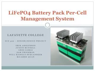
LiFePO4 Battery Pack Per-CellManagement System William kiewicz-schlansker Lafayette college
System Overview • Lafayette Photovoltaic Research and Development System (LPRDS) • 2kW solar energy system that converts high voltage DC to 120V AC RMS signal of 60Hz • Capstone project to introduce students to real engineering project issues and requirements • Multi-year multi team senior Electrical and Computer Engineering design project
Why Balance? • Extend useful lifetime • Or, not decrease the expected lifetime • Increased health over lifetime • Increased operational capacity • Increase the accuracy of SOC calculations
Why Balance Our Way? • Dictated by several factors: • Requirements • Physical limitations • Time constraints • Design for simplicity: • Relatively simple implementation • Uses easy to gather information • Can be updated to reflect better cell characterization
Active Vs. Passive Balancing • Active: Using capacitive or inductive loads to shuttle charge from higher charged cells to lower charged cells. • Is more efficient from a power perspective • Has scalability issues • Passive: Bypasses cells (usually through a resistance) and burns off the excess charge from the cell. • Better large-stack scaling • Burn off can be significant
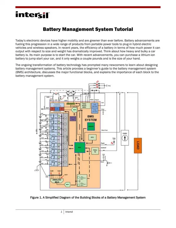
Hardware Design • Strict Physical Requirements • Fit on top of a pack • Low enough to fit in rack • Interweave components between the cell terminals • Electrical Requirements • High power path must handle up to 25 Amps • Minimize current drawn for circuitry • Electrical isolation for all communication signals • Bypass circuitry should bypass as much current as possible
Software Design – Cell Balancing Algorithm • Based on monitoring for 50 mV differences in cell voltages • Maximum and minimum charge decided by hard voltage thresholds • Incorporates temperature measurements to protect against overheating
Software Design – State of Charge Algorithm • Based on Coulomb Counting • Uses data from the current sensor to sum the current over time • Sum and sample period are output through I2C, and the user can calculate SOC by
Conclusions • Standard deviation of cell voltages is a fair metric of the effectiveness of the CBA • Effective operational capacity of the balanced cells demonstrates a noticeable increase over the unbalanced cells
Future Work • Integrate power dissipated to calculate joules used during balancing • Show that joules dissipated and standard deviation flatten off as time increases • Create a merit of efficiency by comparing the joules used during balancing to the increased operational capacity • Full stack integration incorporating a master device • Full system integration with the LPRDS system