Chapter 9: Maintaining and Troubleshooting Network Security Implementations
940 likes | 1.26k Vues
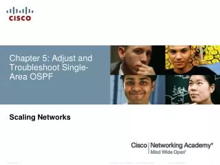
Chapter 9: Maintaining and Troubleshooting Network Security Implementations. CCNP TSHOOT: Maintaining and Troubleshooting IP Networks. Chapter 9 Objectives. Troubleshoot Secure Networks Troubleshoot Management Plane Security Troubleshoot Control Plane Security

Chapter 9: Maintaining and Troubleshooting Network Security Implementations
E N D
Presentation Transcript
Chapter 9:Maintaining and Troubleshooting Network Security Implementations CCNP TSHOOT: Maintaining and Troubleshooting IP Networks
Chapter 9 Objectives • Troubleshoot Secure Networks • Troubleshoot Management Plane Security • Troubleshoot Control Plane Security • Troubleshoot Data Plane Security • Troubleshoot Branch Office and Remote Worker Connectivity
Section Overview • The focus of this section is on the types of network security implemented and their impact on the troubleshooting process. • Security measures that affect troubleshooting can include: • Limiting access to network infrastructure devices • Control and management plane hardening • Packet filtering on routers and switches • Virtual private networks (VPN) • Intrusion prevention system (IPS) features. • It is important to understand which features are deployed and how they operate. • Most security features operate at the transport layer and above. • A generic troubleshooting process can help to determine if problems are related to security features or caused by underlying Layer 1, 2, or 3 connectivity issues. • Reported problems and possible solutions need to be validated against the organization’s security policy. • Depending on the organization, it may be necessary to escalate the issue to a security specialist.
Security Features Review – Functional Planes • Security features can affect router and switch operation on different planes. The three main functional planes are: • Management plane: • Represents functions and protocols involved in managing the device. • Provides access for device configuration, device operation, and statistics. • If the management plane is compromised, other planes are also exposed. • Protocols include Telnet, AAA, SSH, FTP, TFTP, SNMP, syslog, TACACS+, RADIUS, DNS, NetFlow and ROMMON. • Control plane: • Represents functions and protocols between network devices to control the operation of the network. • Layer 3 protocols include routing protocols and HSRP. • Layer 2 protocols and functions include ARP, STP and VLANs. • Data plane: • Represents functions involved in forwarding traffic through the device. • Traffic is between endpoints such as workstations, servers and printers. • Routers and switches can inspect and filter traffic as part of the implementation of a security policy. • All management and control plane traffic flows through the data plane. • Security features on the data plane can cause failures on the management and control plane.
Troubleshooting Management Plane Security The management functions of a router or switch are commonly accessed using three methods: • The Cisco IOS command-line interface (CLI) • Web-based device management • A network management platform based on Simple Network Management Protocol (SNMP) CLI Management Access: • The CLI is the most common and powerful method to manage routers and switches. • Commands are entered through a console connection or remotely through Telnet or SSH. • Authentication ensures that only authorized personnel can access and configure the network devices. • Restrict the network locations that devices can be accessed from and use SSH instead of Telnet. • Physical security is vital to the security of the management plane. • The CLI can always be accessed through the serial console. • An unauthorized user could power cycle the device and use password recovery to gain control of the device.
Management Plane Security – Cont. Web-based Management Access • A web-based device manager can provide an alternative method to manage routers and switches. • Examples include: • Cisco Configuration Professional (CCP) • Security Device Manager (SDM) • The protocol used is either HTTP or HTTPS (preferred). SNMP Management Access • Primarily used to access operational parameters and statistics of the device, not to change the configuration. • If a device is configured for read-access the configuration cannot be changed. • If a device is configured for read-write access, apply the same level of security as for command-line or web-based access.
Management Plane Security: AAA • Authentication, authorization, and accounting (AAA) is a major component of network security. • A centralized security server contains security policies that define the list of users and what they are allowed to do. • Cisco Secure Access Control Server (ACS) is an example of a AAA server. • Network devices can access the centralized security server using protocols such as TACACS+ and RADIUS.
Securing the Management Plane From a troubleshooting standpoint, it is important to know the answer to the following questions: • What security policies have been implemented for management access to the devices? • From which IP addresses or networks can the network devices be accessed? • What type of authentication, authorization, and accounting is used on the network? • If centralized AAA services are deployed, what happens when these servers fail or become unreachable? • Are there any backdoors or fallback mechanisms to access the devices?
Securing the Management Plane - ACS Cisco Secure ACS offers centralized command and control for all user authentication, authorization, and accounting from a web-based, graphical interface. The Reports and Activity screen is shown here.
Securing the Management Plane: ACS – Cont. The ACS Reports and Activity option provides the following to troubleshoot AAA-related problems: • Accounting Reports: • Provided for ACACS+ and the RADIUS • Contains a record of all successful authentications during a time period. • Information includes time, date, username, type of connection, amount of time logged in, and bytes transferred. • Administration Reports: • Contains all TACACS+ commands requested during a time period • Typically used when ACS is being used to manage access to routers. • Passed Authentications: • Lists successful authentications during a time period. • Failed Attempts: • Contains a record of all unsuccessful authentications during a time period (for both TACACS+ and RADIUS). • Captures the username attempted, time, date, and cause of failure. • Logged-in Users: • Shows all users currently logged in, grouped by AAA client. • Disabled Accounts: • Contains accounts that have been disabled.
Management Plane Authentication: AAA/TACACS+ The debug tacacs and debug aaa authentication commands can be useful for troubleshooting AAA authentication problems. The example shows the output for a successful login attempt using TACACS+. Router# debug tacacs Router# debug aaa authentication 13:21:20: AAA/AUTHEN: create_user user=’’ ruser=’’ port=’tty6’ rem_addr=’10.0.0.32’ authen_type=1 service=1 priv=1 13:21:20: AAA/AUTHEN/START (0): port= ‘tty6’ list=’’ action=LOGIN service=LOGIN 13:21:20: AAA/AUTHEN/START (0): using “default” list 13:21:20: AAA/AUTHEN/START (70215483): Method=TACACS+ 13:21:20: TAC+ (70215483): received authen response status = GETUSER 13:21:20: AAA/AUTHEN (70215483): status = GETUSER 13:21:23: AAA/AUTHEN/CONT (70215483): continue_login 13:21:23: AAA/AUTHEN (70215483): status = GETUSER 13:21:23: AAA/AUTHEN (70215483): Method=TACACS+ 13:21:23: TAC+ : send AUTHEN/CONT packet 13:21:23: TAC+ (70215483): received authen response status = GETPASS 13:21:23: AAA/AUTHEN (70215483): status = GETPASS 13:21:27: AAA/AUTHEN/CONT (70215483): continue_login 13:21:27: AAA/AUTHEN (70215483): status = GETPASS 13:21:27: AAA/AUTHEN (70215483): Method=TACACS+ 13:21:27: TAC+ : send AUTHEN/CONT packet 13:21:27: TAC+ (70215483): received authen response status = PASS 13:21:27: AAA/AUTHEN (70215483): status = PASS
Management Plane Authentication: AAA/TACACS+ - Cont. The debug output captured in the example shows the following events: • A remote user with the IP address 10.0.0.32 attempts to log in to the router. • The router checks to see whether AAA authentication for the LOGIN service is enabled (and it is). • Because no other authentication method list is applied, the router applies the default method, and the first method defined by the default method list is TACACS+. • The router authentication process prompts the user for a username and password. • Upon receiving these credentials, the router sends them to the TACACS+ server for verification. • The TACACS+ server checks the credentials against its database and responds with a PASS status as a sign of successful authentication.
Management Plane Authorization: AAA/TACACS+ The debug aaa authorization output captured in this example shows the following events: • The user (admin1) attempts to obtain an EXEC shell service, which requires authorization. • The cmdparameter specifies a command that the user is trying to execute. If * is listed, it refers to plain EXEC access. • The method used to authorize this access is TACACS+. • The router sends the necessary information (user credentials) through TACACS+ to the security server. • The security server verifies the authorization, determines that the user is not authorized to perform this function, and sends back a FAIL status response. Router# debug aaa authorization 2:23:21: AAA/AUTHOR (0): user= ‘admin1’ 2:23:21: AAA/AUTHOR (0): send AV service=shell 2:23:21: AAA/AUTHOR (0): send AV cmd* 2:23:21: AAA/AUTHOR (342885561): Method=TACACS+ 2:23:21: AAA/AUTHOR/TAC+ (342885561): user=admin1 2:23:21: AAA/AUTHOR/TAC+ (342885561): send AV service=shell 2:23:21: AAA/AUTHOR/TAC+ (342885561): send AV cmd* 2:23:21: AAA/AUTHOR (342885561): Post authorization status = FAIL
Management Plane Accounting: AAA/TACACS+ • The debug aaa accountingoutput captured in the example shows a scenario where the default method was used, and that a user successfully gained access to the router’s EXEC shell. Router# debug aaa accounting May 10 14:48:33.011: AAA/ACCT/EXEC(00000005): Pick method list ‘default’ May 10 14:48:33.011: AAA/ACCT/SETMLIST(00000005): Handle 0, mlist 81CA79CC, Name default May 10 14:48:33.011: Getting session id for EXEC (00000005): db=82099258 May 10 14:48:33.011: AAA/ACCT/EXEC(00000005): add, count 2 May 10 14:48:33.011: AAA/ACCT/EVENT(00000005): EXEC UP
Management Plane: Common TACACS+ Issues Common TACACS+ failures can include the following: • A TACACS+ server goes down or a device (TACACS client) cannot connect to the server. As a backup, configure the network device to use the local database for authenticating critical users. • A device (client) shared key and the server’s shared key do not match. • User credentials (username, password, or both) are rejected by the server.
Management Plane: TACACS+ Issues – Cont. Router# debug tacacs Router# debug aaa authentication ! The TACACS+ server is down or the device has no connectivity to the server: TAC+: TCP/IP open to 171.68.118.101/49 failed- Connection refused by remote host AAA/AUTHEN (2546660185): status = ERROR AAA/AUTHEN/START (2546660185): Method=LOCAL AAA/AUTHEN (2546660185): status = FAIL As1 CHAP: Unable to validate response. Username chapuser: Authentication failure ! The key on the device and TACACS+ server do not match: TAC+: received bad AUTHEN packet: length = 68, expected 67857 TAC+: Invalid AUTHEN/START packet (check keys) AAA/AUTHEN (1771887965): status = ERROR ! Bad user name, bad password, or both: AAA/AUTHEN: free_user (0x170940) user= ‘chapuser’ ruser= ‘’ Port= ‘Async1’ rem_addr= ‘async’ authen_type=CHAP service=PPP priv=1 TAC+: Closing TCP/IP 0x16EF4C connection to 171.68.118.101/49 AAA/AUTHEN (2082151566): status = FAIL As1 CHAP: Unable to validate Response. Username papuser: Authentication failure
Management Plane: Common RADIUS Issues • The common RADIUS problems are similar to the common TACACS+ problems: • The RADIUS server’s failure or loss of network connectivity • Mismatch of the shared key between the RADIUS server and the network device (RADIUS client) • User authorization failure (incorrect username, password, or both) • Mismatch of RADIUS port numbers between the router and RADIUS server
Management Plane: RADIUS Issues – Cont. Router# debug radius Router# debug aaa authentication ! The RADIUS server is down or the device has no connectivity to the server: As1 CHAP: I RESPONSE id 12 len 28 from “chapadd” RADIUS: id 15, requestor hung up. RADIUS: No response for id 15 RADIUS: No response from server AAA/AUTHEN (1866705040): status = ERROR AAA/AUTHEN/START (1866705040): Method=LOCAL AAA/AUTHEN (1866705040): status = FAIL As1 CHAP: Unable to validate Response. Username chapadd: Authentication failure As1 CHAP: 0 FAILURE id 13 len 26 msg is “Authentication failure” ! The key on the device and RADIUS server do not match: RADIUS: received from id 21 171.68.118.101:1645, Access-Reject, len 20 RADIUS: Reply for 21 fails decrypt NT client sends ‘DOMAIN\user’ and Radius server expects ‘user’: RADIUS: received from id 16 171.68.118.101:1645, Access-Reject, len 20 AAA/AUTHEN (2974782384): status = FAIL As1 CHAP: Unable to validate Response. Username CISCO\chapadd: Authentication failure As1 CHAP: 0 FAILURE id 13 len 26 msg is “Authentication failure” ! Username and password are correct, but authorization failed: RADIUS: received from id 19 171.68.118.101:1645, Access-Accept, len 20 RADIUS: no appropriate authorization type for user AAA/AUTHOR (2370106832): Post authorization status = FAIL AAA/AUTHOR/LCP As1: Denied ! Bad username, bad password, or both: RADIUS: received from id 17 171.68.118.101:1645, Access-Reject, len 20 AAA/AUTHEN (3898168391): status = FAIL As1 CHAP: Unable to validate Response. Username ddunlap: Authentication failure As1 CHAP: 0 FAILURE id 14 len 26 msg is “Authentication failure” As1 PPP: Phase is TERMINATING
Troubleshooting Control Plane Security • Control plane traffic is handled by the system’s route processor. • Packets that traverse the control plane are those destined for that router’s CPU, as opposed to network endpoints. • Examples include routing protocols, keepalives, first-hop redundancy protocols (FHRP), DHCP, STP and ARP. • All packets entering the control plane are redirected by the data (forwarding) plane. • Denial-of-service (DoS) attacks on the control plane can overburdened router CPU. • Unauthorized participation in any of these protocols should be prevented to secure the network.
Securing the Control Plane: Overview • Most routing protocols support neighbor authentication based on MD5 hashes. • Authentication is also supported by first-hop redundancy protocols: • Hot Standby Router Protocol (HSRP) • Virtual Router Redundancy Protocol (VRRP) • Gateway Load Balancing Protocol (GLBP) • Using an authentication mechanism prevents unauthorized devices from and misdirecting or black-holing application traffic. • The IEEE 802.1D STP does not have an authentication mechanism. • Cisco switches support features such as BPDU guard and Root Guard to help prevent unauthorized interaction with Spanning Tree Protocol. • The DHCP and ARP protocols can be secured by enabling the DHCP snooping and dynamic ARP inspection (DAI) features. • Control plane and control plane protection can use the Cisco Modular QoS CLI (MQC) to protect the infrastructure from DoS attacks.
Securing the Control Plane: Overview – Cont. • It is important to know which control plane security features have been implemented in the network and on which devices. • Misconfiguration can cause the operation of a control plane protocol between devices to fail. • Ask the following questions to help troubleshoot control plane security implementations: • Are routing protocols or FHRPs set up for authentication properly? • Are STP security features such as BPDU Guard, BDPU Filter, Loop Guard, or Root Guard enabled correctly? • Is DHCP snooping configured properly? • Is the configuration of DAI correct? • Are the configurations for control plane policing or control plane protection done appropriately?
Troubleshooting Data Plane Security • Routers and switches process and forwarding network traffic and can play an effective role in inspecting and filtering traffic as it flows through the network. • The Cisco IOS firewall software provides enhanced security functions for the data plane. • There are two types of Cisco IOS firewall: • Classic Cisco IOS firewall (stateful packet inspection) • Zone-based policy firewall
Using IOS Stateful Packet Inspection (SPI) • Cisco IOS stateful packet inspection (SPI) is a component of the Cisco IOS firewall. • Formerly known as context-based access control (CBAC) • Cisco SPI allows certain incoming flows by first inspecting and recording flows initiated from the trusted network. • It is configured per interface and operates by dynamically modifying access list entries based on traffic flows. • IOS SPI can inspect to the application layer • The combination of the inspection policy and the ACL-based policy defines the overall firewall policy. • To protect a trusted (internal) network from an untrusted (external) network using a router with two interfaces, the router can be placed between the two networks. There will be four logical points at which the router can inspect traffic: • Inbound on the internal interface • Outbound on the external interface • Inbound on the external interface • Outbound on the internal interface
IOS SPI Example In the figure, all traffic from the internal LAN to the Internet is allowed and traffic flowing from the Internet toward the LAN is denied.
IOS SPI Example – Cont. • First apply a simple access list to deny all IP traffic for the inbound direction of the external interface (Fa 0/0). In this example an ACL Denying All Inbound Traffic Is Created and Applied to Fa 0/0. Router(config)# ip access-list extended DENY_ALL Router(config-ext-nacl)# deny ip any any Router(config-ext-nacl)# exit Router(config)# interface fa0/0 Router(config-if)# ip access-group DENY_ALL in Router(config-if)# exit
IOS SPI Example – Cont. • To allow responses to return from the Internet for internal client web requests, define an inspection rule to track HTTP sessions. • Create an inspection rule called inshttpto monitor HTTP and apply it outbound on the external interface (Fa0/0). • The router will inspect traffic originating from the trusted network, and dynamically adjust the ACL restricting traffic inbound on the external interface. Router(config)# ip inspect name inshttp http Router(config)# interface fa0/0 Router(config-if)# ip inspect inshttp out Router(config-if)# end Router#
IOS SPI Example – Cont. The output of the show ip inspect sessions in the figure shows that trusted host 192.168.0.2 has opened an HTTP connection to external web server 10.0.0.2
IOS SPI Example – Cont. Use the show ip inspect all command to display the SPI configuration and session information. Router# show ip inspect all Session audit trail is enabled Session alert is enabled <output omitted> Inspection Rule Configuration Inspection name inshttp http alert is on audit-trail is on timeout 3600 https alert is on audit-trail is on timeout 3600 Interface Configuration Interface FastEthernet0/0 Inbound inspection rule is not set Outgoing inspection rule is inshttp http alert is on audit-trail is on timeout 3600 https alert is on audit-trail is on timeout 3600 Inbound access list is DENY_ALL Outing access list is not set <output omitted>
IOS SPI Example – Cont. An audit trail can be enabled to generate syslog messages for each SPI session creation and deletion using the ip inspect audit-trailcommand. The output of the debug ip inspectcommand provides greater detail. Router(config)# ip inspect audit-trail Router(config)# %FW-6-SESS_AUDIT_TRAIL_START: Start http session: initiator (192.168.0.2:10032) –– responder (10.0.0.10:80) Router# debug ip inspect Object-creation INSPECT Object Creations debugging is on Router# CBAC* OBJ_CREATE: Pak 6621F7A0 sis 66E4E154 initiator_addr (192.168.0.2:10032) responder_addr (10.0.0.10:80) initiator_alt_addr (192.168.0.2:10032) responder_alt_addr (10.0.0.2:80) CBAC OBJ-CREATE: sid 66E684B0 acl DENY_ALL Prot: tcp Src 10.0.0.10 Port [80:80] Dst 192.168.0.2 Port [10032:10032] CBAC OBJ_CREATE: create host entry 66E568DC addr 10.0.0.10 bucket 8 (vrf 0:0) insp_cb 0x66B61C0C
Zone-Based Policy Firewall Overview • The zone-based policy firewall (ZPF) is the most current Cisco firewall technology. • ZPF allows grouping of physical and virtual interfaces. • Firewall policies are configured on traffic moving between zones. • ZPF simplifies firewall policy troubleshooting by applying explicit policy on interzone traffic. • Firewall policy configuration is very flexible. • Varying policies can be applied to different host groups, based on ACL configuration. • ZPF supports the following functionalities: • Statefulinspection • Application inspection: IM, POP, IMAP, SMTP/ESMTP, HTTP URL filtering • Per-policy parameter • Transparent firewall • Virtual Routing and Forwarding (VRF)-aware firewall
ZPF Example Topology Zone-Based Policy firewall application with private, public and DMZ zones controlled by multiple policies .
ZPF Configuration Example: Process The following steps describe an example process for configuring a simple ZPF between the private and public zones. • Create an inspect class map called MY-CLASS for all TCP-based traffic that matches an ACL (Telnet, SMTP, FTP, and HTTP). • Create a policy map called MY-POLICY which defines the action to perform on the traffic matching the class map MY-CLASS. In this example, the action is to inspect the traffic to create dynamic inspection objects. • Define the two security zones, in this case PRIVATE and PUBLIC. • Create a corresponding zone pair called PRIV-PUB to represent the direction of the traffic to which the policy will be applied. • Apply the policy MY-POLICY to the zone pair to control the traffic. • Zone pair PRIV-PUB states that all traffic sourced from zone PRIVATE and destined for zone PUBLIC will be processed according to policy map MY-POLICY. • Assign each interfaces to an appropriate zone. Interface Fa0/0 is in zone PRIVATE, and interface Fa0/1 is in zone PUBLIC. • Define the ACL to be used by class map MY-CLASS.
ZPF Configuration Example: Commands ! Define inspect class-maps: class-map type inspect match-any TCP match protocol tcp class-map type inpsect match-all MY-CLASS match access-group 102 match class-map TCP ! Define inspect policy-map: policy-map type inspect MY-POLICY class type inspect MY-CLASS inspect ! Define zones: zone security PRIVATE zone security PUBLIC ! Establish zone pair, apply policy: zone-pair security PRIV-PUB source PRIVATE destination PUBLIC service-policy type inspect MY-POLICY ! Assign interfaces to zones: interface FastEthernet0/0 zone-member security PRIVATE interface FastEthernet0/1 zone-member security PUBLIC ! Define ACL access-list 102 permit tcp any anyeq telnet access-list 102 permit tcp any anyeqsmtp access-list 102 permit tcp any anyeq ftp access-list 102 permit tcp any anyeq www
Other Methods of Securing the Data Plane • Unauthorized or unwanted traffic can be blocked by implementing traffic-filtering and other security features such as: • Standalone Access Control Lists (ACLs) • VLAN access maps (on LAN switches) • Cisco IOS firewall (SPI or ZPF) • Intrusion Prevention System (IPS) • Unicast Reverse Path Forwarding (uRPF). • IP Security (IPsec) • IEEE 802.1X • Network Admission Control (NAC)
Troubleshooting Data Plane Security – Cont. • Knowledge of which security features are implemented and where is critical. • Misconfigured security features can cause valid traffic to be dropped. • Security features should always be considered as a possible cause of network connectivity problems. • If there is network layer connectivity between two hosts, but upper layers are not functioning as expected, packet filtering may be a factor. • Management and control traffic also passes through the data plane and data plane security features could be the cause of the failure. • The troubleshooting tools for the ZPF are similar to the tools used for classic Cisco IOS firewall: • When audit trails are enabled, syslog messages are generated for each stateful inspection session. • Debugging can be used to obtain more detailed information in either case
Troubleshooting ZPF Using Syslog - Example • A user complains that he is unable to browse to a web server with the IP address 172.16.1.100. • An administrator searches the syslog for the string 172.16.1.100 and realizes that a Java applet reset option was configured on the ZPF. • The class map is myClassMap, and the appl-class is HttpAic. • The administrator corrects this problem by allowing the embedded Java applet to the server in the HTTP AIC policy (HttpAic). • Syslog is an effective troubleshooting tool available for ZPF. It captures alert, audit trail, and debug command output. May 31 18:02:34.739 UTC: %FW-6-SESS_AUDIT_TRAIL_START: (target:class)- publicPrivateOut:myClassMap:Start http session: initiator (10.1.1.100:3372) –– responder (172.16.1.100:80) May 31 18:02:34.907 UTC: %APPFW-4-HTTP_JAVA_APPLET: HTTP Java Applet detected - resetting session 172.16.1.100:80 10.1.1.100:3372 on zone-pair publicPrivateOut class myClassMap appl-class HttpAic May 31 18:02:34.919 UTC: %FW-6_SESS_AUDIT_TRAIL: (target:class)- (publicPrivateOut:myClassMap):Stop http session: initiator (10.1.1.100:3372) sent 297 bytes –– responder (172.16.1.100:80) sent 0 bytes
Troubleshooting ZPF Using show Commands • show zone security: Displays information for all zones configured and corresponding member interfaces. Verifies zone configuration and assignment. • show zone-pair security (See example): Provides information about how zones are paired including Zone-pair direction (with respect to the traffic flow) and policy applied to zone-pair traffic. • show policy-map type inspect: Displays relevant information for the policy including what traffic is matched to which class and what action is applied to each class of traffic. Also displays the dynamically created session objects. Router# show zone-pair security source PRIVATE destination PUBLIC Zone-pair name PRIV-PUB Source-Zone PRIVATE Destination-Zone Public Service-policy MY-POLICY
Branch Office and Remote Worker Connectivity Branch office connectivity involves multiple topics and technologies such as WAN connectivity through VPNs, Generic Routing Encapsulation (GRE) tunnels, routing, LAN services and security
Branch Office & Remote Worker Connectivity Issues • Site-to-site VPN connectivity • Misconfigured parameters causing mismatches on the VPN-termination routers. • Overlapping IP subnets on the opposite sides of the tunnel which can require the use of NAT • Remote-access VPNs • Host issues related to client configuration or antivirus software. • User authentication and authorization is also a critical function • GRE tunnels • Misconfiguring tunnel source and destination can cause routing issues preventing the tunnel from forming.
Branch Office Connectivity Issues with GRE • GRE tunnels are typically used to transport routing protocols across IPsec VPNs. • Maximum transmission unit (MTU) and fragmentation are a common issue. • Problems related to GRE tunnel establishment are usually due to configurations of tunnel sources and tunnel destinations, along with improper routing of loopbacks. • Firewalls and traffic filters may block the IPsec traffic that carries the GRE tunnels. • Multiple GRE point-to-point tunnels can saturate the physical link with routing information if the bandwidth is not adequately provisioned or configured on the tunnel interface. • The point-to-point nature of traditional GRE tunnels makes a full-mesh solution a challenge because all routers have to terminate a high number of tunnels. • Technologies that can alleviate the full-mesh requirement, making it dynamic, automatic, and efficient can be deployed. Examples include: • Virtual Tunnel Interface (VTI) • Dynamic Multipoint VPN (DMVPN) • Group-Encrypted Transport VPN (GET VPN).
Branch Office Connectivity Issues with GRE – Cont. • Misconfiguration of routing over GRE tunnels can lead to recursive routing. • In the example shown in the figure, the GRE tunnel is terminated at the loopback interfaces of the routers at each end. • Those loopback interfaces are also injected into EIGRP, and they are advertised across the tunnel to the other side, from R3 to R1 and vice versa. • The routing tables will show that the best path to the loopbacks, the source of the tunnel, is the tunnel itself. This causes the inconsistent routing that leads to the recursive routing problem. • When the best path to the tunnel destination is through the tunnel itself, recursive routing causes the tunnel interface to flap. • This might occur by just enabling a routing protocol such as EIGRP over the tunnel.
Branch Office Connectivity Issues – Cont. • Other considerations with respect to troubleshooting branch connectivity include: • Are there firewalls or access lists blocking the VPN traffic? • Are there overlapping subnets at the opposite ends of the tunnel? • Is asymmetric routing causing VPN tunnels to fail? • Do we have HSRP aligned with VPN high-availability functions? • These issues deal with the routing, addressing, and high-availability infrastructures present in the network. • They are necessary for branch connectivity and require additional troubleshooting when they fail. • Because branch connectivity touches so many areas, the tool box for troubleshooting its deployments include showand debugcommands in many areas.
BO/RW Troubleshooting Example – Main Diag. The troubleshooting examples presented in this section are all based on the network topology diagram shown here, with changes to accommodate for different scenarios. The diagram shows a private WAN and an Internet option for branch connectivity. There is also a remote-access service for mobile users and traveling users.
BO/RW TSHOOT Example 1: Address Translation Error • The Branch router is using an IPsec tunnel to provide connectivity to headquarters for its LAN users. • This deployment has been working for a while, but a recent change in NAT configuration has caused the tunnel to go down, not get reestablished, and VPN connectivity to fail. • This is the only branch experiencing the problem. • Regular Internet access, however, has been restored, and users are able to connect to websites normally.
BO/RW TSHOOT Example 1 – Cont. On the Branch router, use the show ip nat statisticscommand to display NAT information. BRANCH# sh ip nat statistics Total active translations: 1 (1 static, 0 dynamic, 0 extended) Outside interfaces: Serial0/0/0 Inside interfaces: FastEthernet0/0 Hits: 0 Misses: 0 CEF Translated packets: 0, CEF Punted packets: 0 Expired translations: 0 Dynamic mappings: –– Inside Source [Id: 1] access-list 150 pool PUBLIC refcount 0 pool PUBLIC: netmask 255.255.255.0 start 172.16.1.100 end 172.16.1.200 type generic, total addresses 101, allocated 0 (0%), misses 0 [Id: 2] access-list VPN pool VPN_NAT refcount 0 start 10.1.10.10 end 10.1.10.200 type generic, total addresses 191, allocated 0 (0%), misses 0 Queued Packets: 0
BO/RW TSHOOT Example 1 – Cont. • The output shows that the VPN traffic is exempted from “public” translation because it remains private as it goes through the tunnel. • Based on the network topology diagram, the subnets on the opposite sides of the VPN are both using address 10.1.1.0/24 and are overlapping. • NAT is needed to translate VPN traffic into something other than 10.1.1.0/24 on both sides. • Traffic matching the VPN access list is being statically translated into an address from the range 10.1.10.10 to 10.1.10.200. • Traffic from Branch to HQ (destination subnet 10.1.4.0/24), should have its source address translate to an address from the 10.1.3.0/24 subnet. • The traffic leaving the headquarters network should have its source address translated to an address from the 10.1.4.0/24 subnet.