Download
1 / 21
210 likes | 403 Vues
Interface Fracture Toughness of EBPVD TBCs by Cross-Sectional Indentation. Xin Wang and Alan Atkinson Department of Materials, Imperial College. Introduction. Interface Fracture. YSZ. TGO. Bond Coat. Substrate. Driving force: the stored energy in ceramic layers.

E N D
Interface Fracture Toughness of EBPVD TBCsby Cross-Sectional Indentation Xin Wang and Alan Atkinson Department of Materials, Imperial College
Introduction Interface Fracture YSZ TGO Bond Coat Substrate Driving force: the stored energy in ceramic layers
TBC lifetime depends on interplay between the driving force and the resistance to crack propagation Work of interface separation Energy Stored energy Lifetime Thermal exposure Time
Stored energy in TGO . Interface toughness?
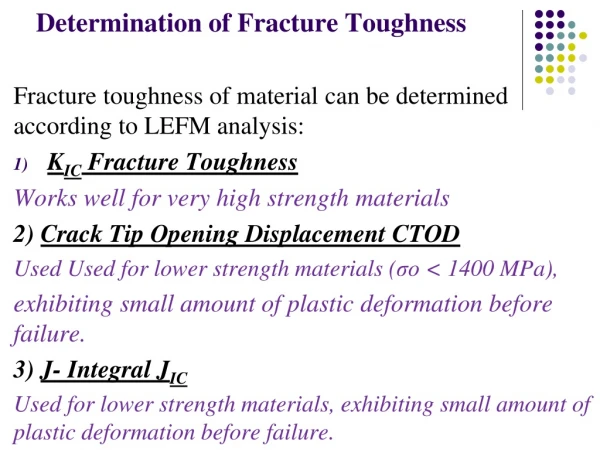
Interface Fracture Test Methods • Stable crack propagation, • Controllable crack propagation, ie., along the interface of interest; • Easiness of cracking observation and measurement • Two major challenges for testing EBPVD TBCs: • Crack path is difficult to control; cracks tend to divert into top coat; • Elastic properties of the top coat is still very poorly characterised
Test Methods for TBCs Top surface Indentation J. Beuth, Eng. Fract. Mechanics, 68(2001), 843 ‘Barb’ shear test Y. Kagawa, Acta. Mater., 56(2008), 43
Cross-sectional Indentation (CSI) Indentation imprint Substrate Interface crack YSZ/TGO SEM Cross sectional image Schematic of CSI
Characterisation of interface cracks Luminescence mapping on top surface Peak shift map (Semicircular delamination) Signal intensity map (TGO/bond coat)
The influence of thermal cycling on interface fracture The delaminated area vs. distance to interface for two different sets of specimens
Crack length affected by stiffening of the topcoat Araldite glue YSZ Substrate 50 cycle
Young’s modulus measurement Free standing specimen was prepared by acid dissolution by HCl acid; YSZ TGO Substrate
Two different test arrangements Loading Loading Column- opening Column- closing
Miniature 3 point bending test 0.03N 0N 0.01N 0.02N 0.04N Column-opening 0N 0.01N 0.03N 0.02N 0.04N Column-closing
Beam profile fitting P -- load, L -- support span I -- second moment of the cross sectional area RO -- radius of the curvature without loading
h R Top surface strain under CSI condition Load: 20 Kg DCI:225μm
A Clamped Circular Plate Model Δμ a EC ----Young’s modulus of the coating HC -----the thickness of the coating a ------the crack length ∆u ------the vertical displacement
Influence of the coating thickness on CSI test Assuming the energy release rate=20 J/ m2 Assuming Ec=40 GPa
Conclusions 1)The stiffness of the top coat in TBCs strongly depends on the strain of the coating: the Young’s modulus of the top coat quickly decreases with the strain in YSZ. 2) The interface toughness may be determined more reliably when top layer YSZ with columnar structure is removed. The Critical energy release rate of TGO/bond interface is about 20 J/m2 for TBCs with Pt-diffusion bond coat thermally cycled for 50 cycles.