Download
1 / 16
230 likes | 631 Vues
Learn about determining fracture toughness through LEFM analysis, KIC value, CTOD, J-Integral, R-Curve, and more. Validate and calculate KIC value, specimen preparation, testing procedure, and fracture toughness in design.

E N D
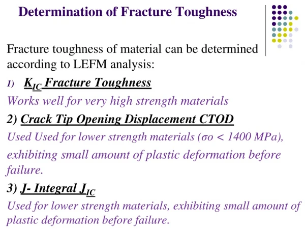
Determination of Fracture Toughness Fracturetoughness of material can be determinedaccordingto LEFM analysis: • KICFractureToughness Works wellforveryhighstrengthmaterials 2) Crack Tip OpeningDisplacement CTOD UsedUsed for lower strength materials (σo < 1400 MPa), exhibiting small amount of plastic deformationbeforefailure. 3) J- Integral JIC Used for lower strength materials, exhibiting smallamount of plastic deformation before failure.
4) R – Curve The resistance to fracture of a material during slow and stable crack propagation. KIC fracture toughness KIC fracture toughness of material is obtained by determiningthe ability of material to withstand the load in the presence of a sharp crack before failure.
Fracture toughness is required inthe system of highstrength andlight weight, i.e., high strength steels, titanium and aluminium alloys. Ex: Flaw geometry and design of cylindrical pressure vessel
Determination of KIC fracture toughness • KIC - thecriticalstressintensity in mode I fracture • Needtomake sure thatthespecimen is testedundermode Ifractureand in a planestraincondition. Therefore, brittleconditionwill be obtained. 1) Validation of KIC fracturetoughnessvalue 2) Specimenpreparation 3) Testingprocedure 4) Calculation of KIC value
Validation of KIC value • Since the stress distribution under the notch varies due to specimen thickness, which also affect toughness of materials of different test specimen dimensions. • Due to the criterion for brittle fracturein the presence of the notch, the planestrain condition, is required for thevalidation of fracture toughness KIC values. Equation *
Specimen preparation • Select the specimen dimensions. • Select the crack propagation direction. • Fatigue pre-cracking by applying fatigue load at a controlled condition ofsmall load and amplitude to obtain a sharpfatigue pre-crack to ensure high stressdistribution ahead of the crack tip.
Test procedure for KIC fracture toughness • A pre-cracked specimen (three point bending specimen) is arranged and monotonically loaded until failure. • Load and clip gauge displacement arerecorded during loading to give a graph,which will be used for calculation.
Calculation of KIC fracture toughness Fracture toughness KQ is calculated using the following expression (for a bend specimen). C(T) Specimen SENB Specimen
Calculation of KIC fracture toughness If the KQ value obtained from above equation is verified according to Equation *, KIC will be obtained. Fracture toughness and design If the KIC value of material is known and the presence ofa crack is allowed, we can then monitor the crack propagationduring service prior to failure. How long we can use the component before it fails. Crack in the component (in service) can be detected by using Non Destructive Testing (NDT), i.e., ultrasonic, dyepenetrant, X-ray, Eddy current, ferromagnetic inspection.
Problem 1:The dimensions and material properties of the AISI 4340 plate made of steel and containing a crack in the center are as given below. This plate has a defect of a = 1mm as an initial crack. Calculate the stress intensity factor for the plate and the crack position as the plate is subjected to a tensile load of P = 240 N. (W = width, B = thickness, H = height. HOMEWORK 1
Problem 2: The fracture toughness of a piece of aircraft made of aluminum is 40MPa(m)1/2. It has been identified that the fracture occurs under 300 MPa stress and the maximum internal crack length reaches 4.0 mm.For the same part and alloy, calculate whether the fracture occurs while 260 MPa stress applied andthe maximum internal crack length reaches 6.0mm?Why?orwhy not? Please explain? ?
Solution 2:Airplane parts are made of aluminum alloy ...If we look at the definition of critical fracture toughness,to provide information about the geometry of. We can use. (Y) is the shape correction factor and it can be used to calculateKI value and after second loading the crack dimension is measured, and the resulting value is compared with fracture toughness value. In the second case fracture will occur because the value of KIis greater than the value of KIC.
If the fracture occurs in the elastic region of the traction curve, therefore as can be seen from the figure we have brittle fracture. Brittle fracture
If the fracture occurs in the plastic region of the traction curve, therefore as can be seen from the figure we have ductile fracture.
Ductile Fracture Overwiev For plastic deformation it should be σapp> σyield. However, even when (σapp) is in the elastic region the fracture can occur Ductile Fracture The stress causing the fracture is (σ).The stress causing the sliding (τ).