Download
1 / 23
250 likes | 552 Vues
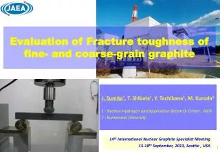
Evaluation of Fracture toughness of fine- and coarse-grain graphite. J. Sumita 1 , T. Shibata 1 , Y . Tachibana 1 , M. Kuroda 2 1 : Nuclear Hydrogen and Application Research Center , JAEA 2 : Kumamoto University. 14 th International Nuclear Graphite Specialist Meeting

E N D
Evaluation of Fracture toughness of fine- and coarse-grain graphite J. Sumita1, T. Shibata1, Y. Tachibana1, M. Kuroda2 1 : Nuclear Hydrogen and Application Research Center , JAEA 2 : Kumamoto University 14thInternational Nuclear Graphite Specialist Meeting 15-18thSeptember, 2013, Seattle , USA
Contents • Introduction • Experiments • Results • Summary
Methodology to confirm the integrity of graphite component in HTTR -Acceptance inspection- In order to remove the components with harmful defects, the non-destructive inspection UT and ET are carried out for the componentsin acceptance inspection. UT : Ultra sonic test, ET : Eddy current test • Components without harmful defects do not fracture through the in-service period on the basis of fracture mechanics.
Methodology to confirm the integrity of graphite component in HTTR -In-service inspection- • In order to confirm the integrity of the graphite components in in-service inspection, • Surveillance test • Mandatory or non-mandatory (depending on necessity) • Visual inspection by TV camera etc. • Mandatory (for HTTR) • If a defect ( > design assumption) is found in graphite components by in-service inspection, • Causes shall be investigated • Propriety of continuous use shall be judged by application of fracture mechanics etc. It is necessary to understand the fracture mechanism of graphite.
Objectives • Previous studies of evaluation on fracture features of graphite • Effect of notch sharpness and size of specimen • Effect of oxidation, etc • Experimental methodology to determine fracturetoughness of graphite (ASTM D7779) • Some qualitative theories for fracture of graphite To characterize fracture features of fine- and coarse-grained graphites • The three-point-bending test is carried out for two kinds of specimens, a fine-and coarse-grained graphite. • The fracture mechanism of both fine- and coarse-grained graphites is investigated.
Contents • Introduction • Experiments • Results • Summary
Material • Fine-grained isotropic graphite G347 (Manufactured by TOKAI CARBON) • Coarse-grained extruded graphite FE250 (Manufactured by TOKAI CARBON) Typical properties of G347 and FE250 *RT – 1000oC http://www.tokaicarbon.co.jp/
Specimen preparation • Single edge notched beam specimen Straight-through notch Specimen geometry • Introduce of notch: razor blade • Notch angle: approximately 15o • Depth and width of notch: profile projector • Cleaning: ethanol and acetone in the ultrasound bath • Root radius and notch angle: laser microscope
Fracture toughness test • Three-point-bending test Three-point-bending test setup • Outer support span: 160 mm • Crosshead speed: 0.1 mm/min • Sampling rate to record load and displacement: 200 Hz
Calculation of fracture toughness • Calculation of value of fracture toughness Fracture toughness KCis given by linear fracture mechanics KC : Fracture toughness(MPa/m1/2) Pmax: Maximum force(N) S: Support span(m) B: Specimen breadth(m) W : Specimen width(m) a: Notch depth(m) The value of the fracture toughness was calculated using the maximum force on the load-displacement curve obtained by the three-point-bending test.
Contents • Introduction • Experiments • Results • Summary
Load-displacement curves • A typical load-displacement curve Load (N) A : across grain Displacement (mm) < G347 FE250A • Slope • Maximum load Pmax • Slope • Maximum load Pmax
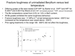
Value of fracture toughness A : across grain, W : with grain Previous study for G347*1 Fracture toughness obtained by CT specimen (1.06 MPa/ m0.5) Fracture toughness obtained by SENB specimen (1.09 MPa/ m0.5) *1 Ekinaga, at. El., INGSM 9 Nearly equal
Fracture toughness of fine-grained graphite *1 Yamada, et. al., HTR2012-4-020 *2Kurumada, et. al., Transaction of the Japanese society of the mechanical engineeras, A,63(608), 838-844, (1997) *3 Matsushima, et. al., M&M 2012 (in Japanese) • The fracturetoughness of fine-grained graphite obtained in accordance with ASTM D7779 is almost the same as that reported in the previous studies. • The value of fracture toughness of the fine-grain graphite is not different from that of the coarse-grain graphite.
Application to HTGR components • Fracture stress σc: Fracture stress (MPa) KIC : Fracture toughness(MPa/m1/2) a: Harmful defect size(m) α : Shape factor The fracture stress depends on the harmful defect size. Fine-grained graphite • Small harmful defect • High fracture stress The employment of fine-grained graphite for core components of the HTGR has some advantages.
Fracture mechanism Grain Crack Pore Binder (pitch) Small Large Grain size • The fracture of graphtie is influenced by pre-existing defects or weak region. • The crack would basically propagate in pore. • If higher stress applied, the crack would propagate in binder. • The crack in both fine-grained and coarse-grained graphite would propagate in pores and binders along with grain boundary. • If the direction of crack growth corresponds to the grain with proper orientation, the crack would propagate inside grain. In order to confirm this mechanism, the cracks propagation are observed.
Observation of crack propagation • Method • Stereomicroscope :OLYMPUS SZX7 • Material :G347, FE250W, FE250A Notch Observed area Crack
Crack observation by stereomicroscope (G347) × Crack The crack seems to propagate straight. × 1000um
Crack observation by stereomicroscope (FE250W) × Crack Inside grain? × The crack seems to propagate in pores and binders. Some cracks seem to propagate inside grain. 1000um
Crack observation by stereomicroscope (FE250A) × Crack Inside grain? The crack seems to propagate in pores and binders. Some cracks seem to propagate inside grain. × • Future works • Polarization microscope, EBSD (electron back scattering diffraction). 1000um
Contents • Introduction • Experiments • Results • Summary
Summary • The fracturetoughness of nuclear grade graphite obtained in accordance with ASTM D7779 is almost the same as that reported in the previous studies. • The value of fracture toughness of the fine-grained graphite is not different from that of the coarse-grained graphite. • The crack in coarse-grained graphite seems to propagate along with grain boundary and some cracks seem to propagate inside grain. • It is planned that the crack propagation in graphite is observed using the polarization microscope and EBSD to confirm the direction of crack growth.