Download

1 / 42
1.06k likes | 2.22k Vues
Week 5 Fracture, Toughness, Fatigue, and Creep. Materials Science. Mechanical Failure. ISSUES TO ADDRESS. • How do flaws in a material initiate failure?. • How is fracture resistance quantified; how do different material classes compare?. • How do we estimate the stress to fracture?.

E N D
Week 5Fracture, Toughness, Fatigue, and Creep Materials Science
Mechanical Failure ISSUES TO ADDRESS... • How do flaws in a material initiate failure? • How is fracture resistance quantified; how do different material classes compare? • How do we estimate the stress to fracture? • How do loading rate, loading history, and temperature affect the failure stress? Computer chip-cyclic thermal loading. Hip implant-cyclic loading from walking. Ship-cyclic loading from waves.
What is a Fracture? • Fracture is the separation of a body into two or more pieces in response to an imposed stress that is static and at temperatures that are low relative to the melting temperature of the material. • The applied stress may be tensile, compressive, shear, or torsional • Any fracture process involves two steps—crack formation and propagation—in response to an imposed stress.
Fracture mechanisms • Ductile fracture • Occurs with plastic deformation • Brittle fracture • Little or no plastic deformation • Catastrophic
Very Moderately Fracture Brittle Ductile Ductile behavior: %AR or %EL Large Moderate Small Ductile vs Brittle Failure • Classification: • Ductile fracture is usually desirable! Ductile: warning before fracture Brittle: No warning
Example: Failure of a Pipe • Brittle failure: --many pieces --small deformation • Ductile failure: --one/two piece(s) --large deformation
Moderately Ductile Failure void growth shearing void necking fracture and linkage at surface nucleation s 50 mm 50 mm • Resulting fracture surfaces (steel) 100 mm particles serve as void nucleation sites. • Evolution to failure:
Ductile vs. Brittle Failure cup-and-cone fracture brittle fracture
Transgranular vs Intergranular Fracture Intergranular Fracture Transgranular Fracture
Brittle Fracture Surfaces • Transgranular (within grains) • Intergranular (between grains) 304 S. Steel (metal) 316 S. Steel (metal) 160mm 4mm Polypropylene (polymer) Al Oxide (ceramic) 3mm 1mm
Ideal vs Real Materials s TS << TS perfect mat’l-no flaws perfect materials engineering materials E/10 carefully produced glass fiber typical ceramic typical strengthened metal E/100 typical polymer e 0.1 • DaVinci (500 yrs ago!) observed... -- the longer the wire, the smaller the load for failure. • Reasons: -- flaws cause premature failure. -- Larger samples contain more flaws! • Stress-strain behavior (Room T):
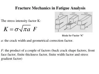
Flaws are Stress Concentrators! Results from crack propagation • Griffith Crack where t = radius of curvature so = applied stress sm = stress at crack tip Kt = Stress concentration factor t
s o max Stress Conc. Factor, K t = s o w s 2.5 max h r , w/h 2.0 increasing fillet radius 1.5 r/h 1.0 0 0.5 1.0 sharper fillet radius Engineering Fracture Design • Avoid sharp corners! s
Crack Propagation Cracks propagate due to sharpness of crack tip • A plastic material deforms at the tip, “blunting” the crack. deformed region brittle Energy balance on the crack • Elastic strain energy- • energy stored in material as it is elastically deformed • this energy is released when the crack propagates • creation of new surfaces requires energy plastic
When Does a Crack Propagate? Crack propagates if above critical stress where • E = modulus of elasticity • s= specific surface energy (J/m2) • a = one half length of internal crack For ductile => replace gs by gs + gp where gp is plastic deformation energy i.e., sm> sc
Fracture Toughness: Design Against Crack Growth K ≥ Kc= --Result 2: Design stress dictates max. flaw size. --Result 1: Max. flaw size dictates design stress. amax s fracture fracture no no amax s fracture fracture • Crack growth condition: • Largest, most stressed cracks grow first!
Fracture Toughness • For relatively thin specimens, the value of Kc will depend on specimen thickness. However, when specimen thickness is much greater than the crack dimensions, Kc becomes independent of thickness. • The Kc value for this thick-specimen situation is known as the plane strain fracture toughness KIC
Graphite/ Metals/ Composites/ Ceramics/ Polymers Alloys fibers Semicond 100 1 C-C (|| fibers) Steels 7 0 6 0 Ti alloys 5 0 4 0 Al alloys 3 0 ) Mg alloys 0.5 2 0 2 Al/Al oxide(sf) 4 Y O /ZrO (p) 2 3 2 1 C/C ( fibers) 10 3 Al oxid/SiC(w) (MPa · m 5 Si nitr/SiC(w) Diamond 7 4 Al oxid/ZrO (p) 2 6 Si carbide 6 Glass/SiC(w) 5 PET Al oxide Si nitride 4 PP Ic 3 PVC K 2 PC 1 <100> 6 Glass PS Si crystal <111> 0.7 Glass - soda Polyester 0.6 Concrete 0.5 Fracture Toughness Kc=
Design Example: Aircraft Wing • Use... --Result: 112 MPa 9 mm 4 mm Answer: • Material has Kc = 26 MPa-m0.5 • Two designs to consider... Design B --use same material --largest flaw is 4 mm --failure stress = ? Design A --largest flaw is 9 mm --failure stress = 112 MPa • Key point: Y and Kc are the same in both designs. • Reducing flaw size pays off!
TS sy larger e TS smaller sy e e Loading Rate • Increased loading rate... -- increases sy and TS -- decreases %EL • Why? An increased rate gives less time for dislocations to move past obstacles and form into a crack. s
(Charpy) final height initial height Impact Testing • Impact loading: -- severe testing case -- makes material more brittle -- decreases toughness
Impact Tests • A material may have a high tensile strength and yet be unsuitable for shock loading conditions • Impact testing is testing an object's ability to resist high-rate loading. • An impact test is a test for determining the energy absorbed in fracturing a test piece at high velocity • Types of Impact Tests -> Izod test and Charpy Impact test • In these tests a load swings from a given height to strike the specimen, and the energy dissipated in the fracture is measured
A. Izod Test • The Izod test is most commonly used to evaluate the relative toughness or impact toughness of materials • Izod test sample usually have a V-notch cut into them • Metallic samples tend to be square in cross section, while polymeric test specimens are often rectangular
Izod Test - Method • It involves striking a suitable test piece with a striker, mounted at the end of a pendulum • The test piece is clamped vertically with the notch facing the striker. • The striker swings downwards impacting the test piece at the bottom of its swing.
Determination of Izod Impact Energy • At the point of impact, the striker has a known amount of kinetic energy. • The impact energy is calculated based on the height to which the striker would have risen, if no test specimen was in place, and this compared to the height to which the striker actually rises. • Tough materials absorb a lot of energy, whilst brittle materials tend to absorb very little energy prior to fracture
B. Charpy Test • Charpy test specimens normally measure 55 x 10 x 10mm and have a notch machined across one of the larger faces • The Charpy test involves striking a suitable test piece with a striker, mounted at the end of a pendulum. • The test piece is fixed in place at both ends and the striker impacts the test piece immediately behind a machined notch.
Factors Affecting Impact Energy • For a given material the impact energy will be seen to decrease if the yield strengthis increased • The notch serves as a stress concentration zone and some materials are more sensitive towards notches than others • Most of the impact energy is absorbed by means of plastic deformation during the yielding. Therefore, factors that affect the yield behavior (and hence ductility) of the material such as temperature and strain rate will affect the impact energy
Effect of Temperature on Toughness • Increasing temperature... --increases %EL and Kc • Ductile-to-Brittle Transition Temperature (DBTT)... FCC metals (e.g., Cu, Ni) BCC metals (e.g., iron at T < 914°C) polymers Impact Energy Brittle More Ductile s High strength materials ( > E/150) y Temperature Ductile-to-brittle transition temperature
Fatigue Test • Fatigue is concerned with the premature fracture of metals under repeatedly applied low stresses • A specified mean load (which may be zero) and an alternating load are applied to a specimen and the number of cycles required to produce failure (fatigue life) is recorded. • Generally, the test is repeated with identical specimens and various fluctuating loads. • Data from fatigue testing often are presented in an S-N diagram which is a plot of the number of cycles required to cause failure in a specimen against the amplitude of the cyclical stress developed
Fatigue Test - S-N Curve • This S–N diagram indicates that some metals can withstand indefinitely the application of a large number of stress reversals, provided the applied stress is below a limiting stress known as the endurance limit
Fatigue Mechanism crack origin • Crack grows incrementally typ. 1 to 6 increase in crack length per loading cycle • Failed rotating shaft --crack grew even though Kmax < Kc --crack grows faster as • Ds increases • crack gets longer • loading freq. increases.
S = stress amplitude Increasingm s near zero or compressive m s moderate tensile m s Larger tensile m N = Cycles to failure --Method 1: shot peening --Method 2: carburizing shot C-rich gas put surface into compression 2. Remove stress concentrators. better bad bad better Improving Fatigue Life 1. Impose a compressive surface stress (to suppress surface cracks from growing)
4. Creep Test • Creep is defined as plastic (or irrevresible) flow under constant stress • Creep is high temperature progressive deformation at constant stress • A creep test involves a tensile specimen under a constant load maintained at a constant temperature. • At relatively high temperatures creep appears to occur at all stress levels, but the creep rate increases with increasing stress at a given temperature.
Creep Test • Creep occurs in three stages: Primary, or Stage I; Secondary, or Stage II, and Tertiary, or Stage III
Creep Test • Stage I occurs at the beginning of the tests, and creep is mostly transient, not at a steady rate. • In Stage II, the rate of creep becomes roughly steady • In Stage III, the creep rate begins to accelerate as the cross sectional area of the specimen decreases due to necking decreases the effective area of the specimen
Creep • Occurs at elevated temperature, T > 0.4 Tm tertiary primary secondary elastic
Secondary Creep Stress (MPa) • Strain rate increases for higher T, s 2 0 0 427°C 10 0 538 °C 4 0 2 0 649 °C 10 -2 -1 10 10 1 e Steady state creep rate (%/1000hr) s • Strain rate is constant at a given T, s stress exponent (material parameter) activation energy for creep (material parameter) strain rate applied stress material const.
• Failure: along grain boundaries. g.b. cavities 100 applied stress 20 Stress, ksi 10 data for S-590 Iron 1 12 16 20 24 28 3 24x103 K-log hr L(10 K-log hr) • Time to rupture, tr function of applied stress temperature 1073K Ans: tr = 233 hr time to failure (rupture) Creep Failure • Estimate rupture time S-590 Iron, T = 800°C, s = 20 ksi
Numerical Problems • Problems 8.1 – 8.10; 8.14 – 8.23; and 8.27