Download
1 / 17
170 likes | 266 Vues
Explore the calculation of kinetic energy flux in tidal flows and assess extraction limits for practical applications. Understand boundary friction factors and identify acceptable energy extraction levels.

E N D
Quantifying the Extraction of Energy from Moving Water with a Free Surface Professor Ian Bryden The University of Edinburgh
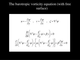
Elevation profile Elevation profile Very easy, in principle, to calculate the kinetic energy flux through the plane shown and express in terms of MW as a function of time! BUT There is more than kinetic energy in a tidal flow AND Always remember, tidal flows are not as simple as many believe
r dA Energy Flux Calculation • Consider the cross sectional plane shown in the idealised channel • Obviously instantaneous flow speed is a function of position r • The instantaneous kinetic energy flux through the plane is give by: • This can be considered alternatively as:
Side View dh h h(x) in h out x Top View b(x) Text book equation for open channel flow Remember the Simple Channel Model • Horizontal channel bed • Linking 2 infinite oceans • Flow driven by a known head dh • Ignore, for now, dynamic effects Q is the discharge rate(m3/s) g is the acceleration due to gravity(m/s2) Per is the wetted perimeter (m) =b+2h 0is the bed sheer stress(kg/m/s2), C is the Chezy friction coefficient
Low Froude Flow • In most realistic channels, the equation simplifies to • At the inlet to the channel, there is a head drop: eff is an effective boundary stress including the influence of artificial energy extraction
Low Froude Flow • The effective boundary friction is given by: • Pext is the total artificial power extraction over the channel length (Watts) • L is the channel length (m) • UC is the longitudinal flow speed characterising the channel (m/s) [in general Uc<U0] • Possible to calculate the channel flow speed for Pext=0
Low Froude Flow • Algebraic manipulation reveals: • This is maximised when: • AND
Kinetic Flux is NOT Enough! • Theoretical absolute limit to extraction in a “simple” channel is given by: • In our test case, L=35km; n=0.035ms-3 A=87,500m2 and R=34m • If =4m/s, • then Pkinetic≈ 2.9 GW • but Pmax ≈ 9.5 GW! Term which accounts for boundary friction and potential drop
Assessing Resource: 1st pass • Identify a suitable site • Establish undisturbed resource • Identify “characteristic” channels • Establish acceptable flow speed reduction in these channels • Use the “B” number procedure to establish practical limit on extraction • Do NOT use the theoretical limit figure X
Constrained Exploitation • Consider a scenario in which we restrict our exploitation to minimise flow disruption. • Accept that energy extraction should not, for example, result in more than 12% flow speed reduction. • This is less than typical turbulence levels!
Identification of Acceptable Extraction Levels • Can identify the value of B* associated with a 12% speed reduction (B*≈0.2) • Use knowledge of L, n and R to determine fabs using the relationship: B*
Our Test Channel • B*=0.2; L=35,000m; R=34m and n=0.035sm-1/3 • Hence: • fabs≈1.7! • This relates to the ratio between the rate of energy extraction and the undisturbed kinetic flux
Determining the Acceptable Power Output • At 4m/s, the “acceptable” energy extraction rate is 4.9GW! • This says nothing about how to actually extract that energy! • If the mean spring peak speed was 4m/s and the mean neap peak was 2m/s, then the mean extractable flux would be approximately 1030MW
Influence of Flow Change on System Design • Large changes in the flow speed will result in requirements for changes in the turbine control system and also system size! • Consider the 100MW tidal farm • This could consist of 50, 21.5m diameter devices, each rated 2MW at 3m/s. • If exploitation results in a 10% flow speed reduction, the diameter will need to be 25m!!
3m/s 2.7m/s There are obvious implications for cost and this is only a 10% reduction in flow speed!