Download
1 / 42
420 likes | 573 Vues
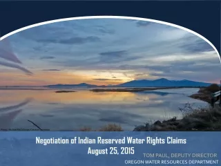
Alex C. MUELLER Deputy Director. ADS (Accelerator- Driven System) Kernreaktoren : Status und Perspektiven. DPG Frühjahrstagung 2011, AKE Sitzung. 2005 World Energy Flow Diagram. Rejected Energy. 229EJ. Primary Energy. Useful Energy. 461 EJ. 232EJ.

E N D
Alex C. MUELLERDeputyDirector ADS (Accelerator-Driven System) Kernreaktoren: StatusundPerspektiven DPG Frühjahrstagung 2011, AKE Sitzung
2005 World Energy Flow Diagram Rejected Energy 229EJ Primary Energy Useful Energy 461 EJ 232EJ Source: Lawrence Livermore National Laboratory chart figures in quads – 1 quad=1.05 EJ
The dilemma of the future energy mix • Hypothese for 2050 • Energy consumption will only increase by a foctor of 2 (energy economies !!) • CO2 emissions will be reduced by a factor of 2 2005 2050 Consommation ~10 Gtep (% de 10 Gtep) 20 Gtep (% de 20 Gtep) Fossiles 7.9 78% : 2 4.1 20% Bio & Waste 1.0 10% x 3 3.3 17% Hydro 0.6 6% x 2 1.2 6% Other Renewables* 0.05 0.5% x 100 5.4 27% Nuclear 0.6 6% x 10 6.0 30% *Solar (thermal and photovoltaic, wind, geothermal, biomasse)
Key technologies for a low carbon energy system Source SET-Plan UE
Total life cycle raw material requirements Source: Marheineke 2002
Generations of nuclear power plants Generation II Generation I • LWR-PWR, BWR • CANDU • HTGR/AGR • VVER/RBMK • Early prototype/demo reactors • Shippingport • Dresden, Fermi I • Magnox Generation IV • Highly economical • Proliferation resistant • Enhanced safety • Minimize waste • First demo of nuclear power on commercial scale • Close relationship with DOD • LWR dominates • Multiple vendors • Custom designs • Size, costs, licensing times driven up from van Heek Groningen Energy Convention 2005 Generation III • ABWR, System 80+, AP600, EPR • Passive safety features • Standardized designs • Combined license Atoms for Peace Tsunami Japan TMI-2 Chernobyl 1950 1960 1970 1980 1990 2000
PresentGen-II Nuclear Power Plants in Europe Worldwide: 440 NPP on grid 560 planned (170 sites)
Nuclear energy makes 880 TWh/y (35% of EU's electricity), but PWR produce important amounts of high level waste • Nuclear Waste from • present LWR's • (Light Water Reactors) • is highly radiotoxic (108 Sv/ton) • at the end of present- type nuclear deployment about 0.3 Mtons, or 3x10¹³ Sv, compare to radiation workers limiting dose of 20mSv • the initial radiotoxicity level of the mine is reached after more than 1 Mio years • worldwide, at present 370 "1GWel equiv. LWR" produce 16% of the net electricity • Geologic time storage of spent fuel is heavily debated • leakage in the biosphère ? • expensive (1000 €/kg), sites? (Yucca mountain would hold 0.07 Mio tons!!) • public opposition
The Yucca Mountain Dilemma • In the United States, the plan is/was to send all spent nuclear fuel to the • Yucca Mountain Repository. The challenge they are faced with is that new • repositories will be needed as nuclear energy continues or grows. Speaker @ Yucca Mountain M. Capiello & G. Imel (ANL) (ICRS-10/RPS2004) EIA 1.5% Growth MIT Study 6-Lab Strategy Spent Fuel (metric tons) Secretarial Recommendation on second repository Constant 100 GWe Capacity based on limited exploration Year Legislatedcapacity
249Cf 250Cf 251Cf 252Cf Z 249Bk 250Bk +n 242Cm 243Cm 244Cm 246Cm 245Cm 247Cm 248Cm 249Cm 244Am 241Am 242Am 243Am 243Pu 239Pu 240Pu 241Pu 242Pu AX β- AX 239Np β- a Emitter b Emitter 238U 239U +n NuclearReaction Flow in a PWR building up MA-waste
blue = neutron capture green = neutron-induced fission
2 1,5 1 0,5 0 -0,5 Pu240 D(TRU) D(Pu) Pu241 -1 Pu238 Np237 Pu242 Am243 Cm244 Pu239 Am242 U238 -1,5 -2 Cm245 -2,5 -3 Neutron consumption per fission ("D-factor") for thermal (red) and fast (blue) neutron spectra • D 0 implies a source of neutrons is required, • whereas D < 0 implies excess neutron self-production thermal neutron "make nuclear waste" and do not use the resource optimally Sustainability = Fast Neutrons
Partitioning and Transmutation for GEN-II/III Partitioning: Separating out of spend fuel certain chemical elements Transmutation: Transforming a chemical element into another Advanced fuel cycles with P/T may greatly benefit to deep geological storage: Reduction of radiotoxicity. Reduction of the heat load larger amount of wastes can be stored in the same repository according to the PATEROS study a “one-order-of-magnitude” reduction in the needed repositories can be expected (a factor of 50 under optimum conditions)
accelerator Proton Beam Spallation Target ADS: Accelerator Driven (subcritical) System for transmutation Both critical (fast!!) reactors and sub-critical Accelerator Driven Systems (ADS) are potential candidates as dedicated transmutation systems. Critical reactors, however, loaded with fuel containing large amounts of MA pose safety problems caused by unfavourable reactivity coefficients and small delayed neutron fraction. ADS operates flexible and safe at high transmutation rate (sub-criticality not virtue but necessity!)
Faisceaux de protons requis Abaques Courant/Energie/Sous-Criticité pour un démonstrateur de 80 MWtherm (simulation par ANSALDO) 10 3 Dépôt de puissance dans le Pb-Bi
PDS-XADS Reference Accelerator Layout Strong R&D & construction programs for LINACs underwayworldwide for many applications (Spallation Sources for Neutron Science, Radioactive Ions & Neutrino BeamFacilities, Irradiation Facilities)
High-power proton CW beams Extrememely high reliability is required !!! Accelerator main specifications
An example of R&D Intermediate-energyRF structure started in FP6 EUROTRANS and continued in FP7 MAX Intermediate Energy Section(3/5 MeV -> 100 MeV) • 2 main types of structures are evaluated • Multi-gap H structures (front end) • Superconducting spoke cavities (independently-phased linac)
Testexperiment in Mol (B): GENEPI-3C coupled to VENUS-F INAUGURATION By Belgian Gvt et High-level F Represetatives 4 March 2010! GENEPI-3C Ventilation room Dipole Accelerator control room Reactor control room VENUS-F core
GENEPI 3C Acelerator IN2P3-LPSC, March 2009
MYRRHA SCK-CEN MYRRHA
CDT Design réacteur SCK●CEN FREYA Expérience GUINEVERE SCK●CEN MAX Design accélérateur CNRS Present R&D for Myrrhawithin FP7 Expériences à basse puissance (monitoring sous-criticité...) Intéractions sur le design de la machine, notamment à l’interface réacteur/accélérateur Feedbacks de l’opération de l’accélérateur
FP7 CDT : The purpose • Build on what has been accomplished up till now in the FP5, FP6 projects and national programmes projects related to this topic (starting from MYRRHA/XT-ADS) • Obtain an advanced design of a flexible fast spectrum irradiation facility working in sub-critical mode (ADS) and critical mode • Set up of a centralised multi-disciplinary team • Based at the Mol-site (core group) • Members from industry and research organisations MYRRHA-D 2005 XT-ADS Myrrha2009 MYRRHA/FASTEF 2012
FP7: refining MYRRHA (1/2) • To be operated as a flexible fast spectrum irradiation facility working in subcritical and critical mode allowing for: • fuel developments for innovative reactor systems; • material developments for GEN IV systems; • material developments for fusion reactors; • radioisotope production; • industrial applications, such as Si-doping; • To allow the study of the efficient transmutation of high-level nuclear waste (MA) requesting high fast flux intensity (Φ>0.75MeV = 1015 n.cm-2.s-1);
FP7: refined MYRRHA objectives (2/2) • To demonstrate the ADS full concept by coupling the three components (accelerator, spallation target and sub-critical reactor) at reasonable power level to allow operation feedback, scalable to an industrial demonstrator; • To contribute to the demonstration of LBE technology and to demonstrate the critical mode operation of a heavy liquid metal cooled reactor as an alternative technology to SFR
The Roadmap for MYRRHA • On March 5, 2010 the Belgian government decided the funding • of the MYRRHA at a level of 40% of the total cost of the project • with a first budget release of 60 M€ for the period 2010-2014 aiming at: • completing the front-end engineering design (FEED) of the project, • securing the licensing of the project • obtaining the construction permit • establishing the international consortium • The main next milestones of the project are as follows: • 2010-2014 : Completion of Front End Engineering Design • 2014 : Obtaining the construction permit • 2014 : Consolidation of the international consortium • 2015 : Tendering and contract awarding • 2016-2018 : Construction of components and civil engineering • 2019 : On-site assembly • 2020-2022 : Commissioning • 2023 : Progressive start-up • 2024 : Full power operation
ADS Demonstrator = MYRRHA Main features of the ADS demo 50-100 MWth power keff around 0.95 600 MeV, 2.5 - 4 mA proton beam Highly-enriched MOX fuel Pb-Bi Eutectic coolant & target
MYRRHA and Gen-IV: a LFR demonstrator Agenda européen pour le développement des démonstrateurs de réacteurs de 4èmegénération
La ligne de faisceau finale Ligne de faisceau en cours de conception (CNRS, projet CDT) • Triple déviation achromatique & télescopique • Robotisée dans le hall réacteur • Arrêt faisceau 2.4 MW • Balayage cible • Diagnostics faisceau Distribution faisceau sur cible
faisceau de protons 1 GeV 100 cm 235 cm 165 cm FromTholière et al.: MUST : MUltiple Spallation Target ADS Trois cibles de spallation P = 3 GWth Itot ~ 100 mA Keff ~ 0.98 Barres de commandes à étudier Crayon Réflecteur Combustible Cible de spallation Assemblage commande Assemblage Assemblage commande
1 2 3 … Flux radiaux avec 3 cibles (fromGuertin et al.) cible spallation cible spallation • Barres de commandes • trop importantes • Chute du flux • au delà des cibles • Nappe de puissance aplatie • « dans » les cibles Neutron fllux (a.u.) Assemblage Neutron fllux (a.u.) Energie moyenne : peu de différences… Exploitation du flux rapide ? Energie (MeV)
8 6 4 1 2 2 Concept MUST à 4 cibles Quatre cibles de spallation P = 3 GWth Itot ~ 100 mA Keff ~ 0.98 Barres de commandes à inclure Neutron fllux (a.u.) AssemblyNumber Le flux de neutrons est distribué de façon plus homogène dans le cœur sous- critique
Strate incinératrice ADS : Puissance unitaire = 3 GWth Taux de disparition d’actinides mineurs : 1319 kg/an Atomes Masse à t = 0 an Masse à t final Np 1.15 t 0.02 t Am 8.51 t 0.97 t Cm 1.57 t 1.01 t 2 ADS pour y parvenir 1kg d’AM : P = 2.5 MWth 2.2 ADS Ordres de grandeurs à l’équilibre Application d’ACDC #1 - Durée de cycle = 7 ans- Multi-recyclé : 237Np, - Durée de refroidissement = 5 + 2 ans 241Am, 243Am - Composition initiale : A.M. sortie RNR/MOX 242Cm, 244Cm Strate électrogène RNR-MOX : Puissance totale = 63.8 GWe Nombre d’unités = 44 réacteurs de 1.45 GWe MNp = 4.6 kg/GWe.an MAm = 34.6 kg/GWe.an MCm = 1.21 kg/GWe.an M A.M. = 40.41 kg/GWe.an Flux d’actinides mineurs : 2578 kg/an
Strate incinératrice ADS : Puissance unitaire = 3 GWth Taux de disparition d’actinides mineurs : 1246 kg/an Atomes Masse à t = 0 an ∆Masse à t final Np 1.64 t 1.46 t Am 6.82 t 5.93 t Cm 2.86 t 1.33 t 4.6 ADS pour y parvenir 1kg d’AM : P = 2.5 MWth 4.7 ADS Ordres de grandeurs à l’équilibre Application d’ACDC #2 - Durée de cycle = 7 ans - Multi-recyclé : 237Np, - Durée de refroidissement = 5 + 2 ans 241Am, 242*Am,243Am, - Composition initiale : A.M. sortie REP/UOX 243Cm,244Cm, 245Cm, 246Cm, 247Cm Strate électrogène REP-UOX : Puissance totale = 63 GWe Nombre d’unités = 49 réacteurs de ~1.3 GWe MNp = 1.83 kg/TWhé 1008 kg/an MAm = 7.25 kg/TWhé 4001 kg/an MCm = 1.25 kg/TWhé 690 kg/an Flux d’actinides mineurs : 5699 kg/an
FP5 FP6 FP7 ADOPT Network - PYROREP - PARTNEW - CALIXPART PARTITION EUROPART-IP Partitioning Cluster ACSEPT EUROTRANS-IP PDS-XADS DM1 DESIGN CDT - MUSE - HINDAS - nTOF_ND_ADS DM2 ECATS MAX BASTRA FREYA DM3 AFTRA Transmutation R&D Clusters - FUTURE - CONFIRM - THORIUM CYCLE FUETRA FAIRFUELS F-BRIDGE PERFORM 60 DM4 DEMETRA - ASCHLIM - MEGAPIE-TEST - TECLA - SPIRE DM5 NUDATRA TESTRA GETMAT ANDES FP 5,6,7 R&D clusters on Partitioning and Transmutation
Concluding Remarks Phasing out of fossile fuel needs to bedone in a sustainableway Nuclear Power likely (?) to increase by factor 2-5 worldwide (possible influence fromJapan Tsunami???) Wastefrompresent (Gen-2), and now-installed (Gen-3) canbe adressed by dedicated transmutation systems (ADS) (fast) Gen-4 concepts "self-incinerate" theirwaste. ADS for taking care of GEN-II/III legacy good progress for a european ADS demonstrator Gen-4 moltensaltreactorwith Thorium producesmuchlesswaste