
Electronics
E N D
Presentation Transcript
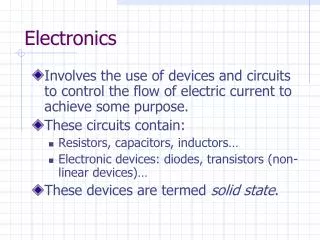
Electronics Topic 6: Transistors
Assumed prior learning 05_01_00 05_01_02 05_02_01 05_03_01 05_04_01
Outcomes By the end of this unit the learner will be able to: • Explain what transistors are and how they work • State what is meant by ”transistor action”
Introduction Finally, we arrive at the king of electronics components – the transistor! In many ways, the story of the 20th Century was the story of the transistor and few inventions have revolutionised the world quite as much. Transistors are at the heart of modern life and make up the brains of most of the electronic stuff we use every day.
The invention that changed the world YT01 Like diodes, transistors are semi-conductors, made from P and N type semi-conductor materials. But it is how these materials are arranged that give transistors their “magical” properties. Before we go on, let’s take a quick detour to learn more about how these tiny little devices have literally changed the world.
The transistor YT02 OK. Change the world. Check! Time to start getting to know these amazing little guys. Watch the video to see a brief introduction to transistors and their history.
Build the Circuit As usual, the best way to find what a component does, is to play with it. Here is the simple circuit you need to build. Build this circuit. Rollover or touch each symbol in the schematic to find out more. Watch the video if you need help. Watch how to build the circuit
Take a picture Take a picture of your completed circuit and upload it to your online portfolio.. Choose image Upload
Review How To Use a Multimeter Img02 We now need to take some readings from our circuit and do some calculations. Refer to the multimeter guide saved on your device or click the image to see it again.
Step 1 Before you connect the battery, do you expect the LED to come on in this circuit? Why or why not? Img03 Set your multimeter to read mA and connect the battery. Take a reading of the current flowing through the LED. What is the current? Current: mA Check
Step 2 Img04 Measure the current through the 50kΩ resistor. Current: mA Check
Step 3 Img05 Close the switch and observe what happens. Measure the current through the LED now. What do you think is happening in the circuit to make the LED shine now? Current: mA Check
Step 4 Img06 Measure the current through the 50kΩ resistor. What is the relationship between this current and that through the LED? Note, you may need to set your multimeter to read μA to get an accurate reading. Current: mA LED current is X 50kΩ resistor current Check
An electronic switch Vid02 In the experiment, we saw that the transistor behaved like a switch. As soon as we allowed current to flow through the 50kΩ resistor and transistor, a current about 100 times larger flowed through the LED part of the circuit. This is called transistor action. Watch the video to see this switch in action.
A night light This simple circuit shows just how useful transistors can be. It is very similar to the previous one we built. Build this circuit. Rollover or touch each symbol in the schematic to find out more. Watch the video if you need help. Watch how to build the circuit
Take a picture Take a picture of your completed circuit and upload it to your online portfolio.. Choose image Upload
Step 1 If the photo resistor has a higher resistance in the dark, when do you think the LED will come on? Img03 Place your circuit is bright light. Does the LED come on? • Yes • No Check
Step 2 Img04 Now place your circuit is the dark or cover the photoresistor with some tape or your hand. Does the LED come on? • Yes • No Check
A night light Vid04 Well done! You just created a working night light. The light only comes on in the dark. But is this an efficient design? Watch the video to check your understanding of how this circuit works.
Semi-conductor review YT03 So far, we have discovered that transistors behave like little electrical switches. But how exactly do they work? In order to under this, we need to first brush up on what we know about semiconductors. YT04 Watch these video to review what we know about semi-conductors.
Semi-conductor sandwiches YT05 We know that diodes are made up of P and N type semiconductor material stuck together. Well, transistors are like semi-conductor sandwiches where we have either a NPN or PNP sandwich. Watch the video to learn how transistors work.
Bi-polar junction transistors NPN The most common type of transistor that you are likely to come across is the bi-polar junction transistor or BJT. BJTs are used when the operating currents are small. There are 2 types of BJTs available. PNP Click on the buttons to learn about each one.
NPN transistors Never Points iN NPN transistors are most common and are made by sandwiching P-type material between 2 layers of N-type material, hence the name NPN. Take note of the symbol and the names of the three leads. If we can get a small current from the base to the emitter, a large current will flow from the collector to the emitter. The arrow in the symbol shows convectional current flow. Collector Collector N P Base Base N Emitter Emitter
PNP transistors Points iN Permanently We can also make a PNP transistor. They are far less common than the NPN type. In this case a small current flowing from the emitter to the base results in a large current flowing from the emitter to the collector. Notice the different symbol used for PNP type transistors. The arrow shows conventional current flow. Emitter Emitter P N Base Base P Collector Collector
NPN vs PNP YT06 NPN and PNP transistors are opposites but things can get a little confusing, so let’s take a moment to make sure we understand the differences between NPN and PNP transistors and how they work. Watch the video for a detailed look at the differences between NPN and PNP transistors.
Build the Circuit We have mentioned before that transistors act as electronic switches and current amplifiers. Let’s explore these a bit more. Build this circuit. Rollover or touch each symbol in the schematic to find out more. Watch the video if you need help. Watch how to build the circuit
Take a picture Take a picture of your completed circuit and upload it to your online portfolio.. Choose image Upload
Review How To Use a Multimeter Img02 We now need to take some readings from our circuit and do some calculations. Refer to the multimeter guide saved on your device or click the image to see it again.
Step 1 Before you connect the battery, make sure that the switch is open. Img03 With the switch open measure the voltage VCE (the voltage over the collector and emitter). VCE V Yes No Is the lamp on? Check
Step 2 Img04 Close the switch and adjust the potentiometer until the lamp is at full brightness. Measure the voltage VCE (the voltage over the collector and emitter) and the voltage over the lamp. VCE V Vlamp V Check
Step 3 Img05 Connect your multimeter across the collector and emitter and adjust the potentiometer until VCE is about 2V, 5V and 7V. What happens to the lamp? VCE = 2V: VCE = 5V: VCE = 7V: Check
Transistor modes Vid06 The previous experiment demonstrated the 2 distinct ways in which a transistor can behave in a circuit which we call: • Switching mode and • Linear mode Watch the video to check your understanding of these modes.
Linear and switching modes? Let’s formalize what we know about what transistors do in a circuit. Click on each button to read more. Switching mode: Transistors can act as current controlled switches. 1 Linear mode: Transistors can act as current amplifiers. 2
Switching mode If current flows between the base and emitter, the transistor switches ON and allows a current to flow between the collector and emitter. This signal determines if the transistor is fully on or fully off. + NPN Base must be at a higher voltage (at least 0.6V) than the emitter and current flows from base to emitter. PNP Base must be at a lower voltage (at least 0,6V) than the emitter and current flows from emitter to base. - + -
Linear mode The current that flows between the collector and emitter is a multiple of the current that flows between the base and the emitter. This multiple is called the Beta and given the symbol HFE. For both NPN and PNP transistors. For linear mode operation, we just need to keep IB within certain parameters. IB, and therefore IC are gradually increased and decreased. IC IE IC + IB = IE IB IB IE IC
Virtual transistor action Let’s look at simulated circuits with both NPN and PNP transistors to confirm what we know about transistor action. Vid07 Download and work through the worksheet. Then watch the video to make sure you completed everything correctly. Download the worksheet
Test Yourself We have come to the end of this unit. Answer the following questions to make sure you understand the basics of transistors.
Question 1 Which symbol is for a NPN transistor? b) a)
Question 2 What are the names of the transistor leads. Choose all the correct answers. • Base • Emit • Exit • Collector • Emitter • Basic
Question 3 Drag the names to the correct places on the diagram. Base Collector Emitter Collector Emitter Base
Question 4 Drag the correct voltage supply symbols onto this circuit so as to bias the transistor correctly.
Question 5 Which mode would a transistor be used in to amplify small changes in current? • Linear mode • Switching mode • Amplification mode • Magnification mode
Question 6 Drag the symbols to give the relationship between IE, IC and IB. IE IC + IB = IE + = IC IB + IC = IE IB
Question 7 Which image shows the correct current flow the the circuit when the transistor is on? b) a) d) c)
Question 8 In the case of a NPN transistor which is on, which terminal of VBC is more positive? • B • C • Both the same
Question 9 A NPN transistor has a beta value of 100. If IB is 0.764mA, what can we expect IC to be? • 0.764mA • 7,64mA • 76.4mA • 764mA
Question 10 A PNP transistor as a beta value of 60. If IE is 142mA what is IB? • 180mA • 2mA • 163μA • 2.33mA
Video Briefing – Vid01 • Create a video presented by an expert presenter showing step-by-step how to build the circuit on a breadboard. The presenter needs to explain the following: • How to connect the transistor correctly. The names of the pins (Collector, Base and Emitter) should be mentioned. Orientate the pins with regard to the flat edge of the casing.
Video Briefing – Vid02 Create a video presented by an expert presenter showing and explaining the operation of the transistor in the experiment. With the switch open and the battery disconnected, explain that we would expect the LED to light up Connect the battery – LED does not light up even though it is connected in series with the battery. The transistor must somehow be blocking the current. Measure the LED current to confirm. Measure 50K resistor current to confirm that it is zero – what we expect as the switch is open. Close the switch and observe LED come on. Measure the current through the LED and 50K resistor. Establish that the LED current is about 100 times greater than the 50K resistor current. Explain that as soon as a little bit of current is allowed to enter the transistor through the middle pin (the base), a lot of current can flow through the transistor from the left pin (collector) to the right pin (the emitter) (L/R with respect to flat end of package). Refer to http://everycircuit.com/circuit/5578205225549824 for a simulation of the circuit. Conclude the the transistor acts like a switch – we can open and close it with a small current AND that it acts to amplify the current – ICE = IBE x 100 Use the simulator to show that ICE/IBE is always about 100. This is called the beta and is often referenced as HFE. As the base current is changed, the collector current is also changed.