Download
1 / 68
730 likes | 1.2k Vues
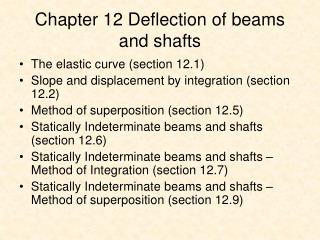
*6.6 COMPOSITE BEAMS. Beams constructed of two or more different materials are called composite beams Engineers design beams in this manner to develop a more efficient means for carrying applied loads Flexure formula cannot be applied directly to determine normal stress in a composite beam

E N D
*6.6 COMPOSITE BEAMS • Beams constructed of two or more different materials are called composite beams • Engineers design beams in this manner to develop a more efficient means for carrying applied loads • Flexure formula cannot be applied directly to determine normal stress in a composite beam • Thus a method will be developed to “transform” a beam’s x-section into one made of a single material, then we can apply the flexure formula
*6.6 COMPOSITE BEAMS • Trial-and-error procedure requires the stress distribution produce a zero resultant force on x-section and moment of stress distribution about neutral axis must be equal to M • A simpler way to satisfy the conditions is to “transform” the beam into one made of a single material
E1 E2 n = *6.6 COMPOSITE BEAMS • Height remains the same, but upper portion of beam widened to carry equivalent load to that carried by material 1. Equation 6-20 • Dimensionless factor n, is called the transformation factor. It indicates that x-section, with a width b on original beam, be increased to a width of b2 = nb in region where material 1 is being transformed into material 2.
*6.6 COMPOSITE BEAMS • Once “transformed”, the normal-stress distribution over the transformed x-section will be linear as shown below.
= n’ *6.6 COMPOSITE BEAMS • For “transformed” material, stress on transformed section has to be multiplied by transformation factor n (or n’) Equation 6-21
*6.6 COMPOSITE BEAMS • IMPORTANT • Composite beams made from different materials to efficiently carry a load • Application of flexure formula requires material to be homogeneous, and x-section of beam must be transformed into a single material
*6.6 COMPOSITE BEAMS • IMPORTANT • Transformation factor is a ratio of the moduli of different materials that make up the beam. It converts dimensions of x-section of composite beam into a beam of single material. • Stress in transformed section must be multiplied by transformation factor to obtain stress in actual beam
EXAMPLE 6.22 Composite beam as shown. If allowable normal stress for steel is (allow)st = 168 MPaand for wood is (allow)w = 21 MPa, determine maximum bending moment beam can support, with and without reinforcement. Est = 200 GPa, Ew = 12 GPa, Moment of inertia of steel beam is Iz = 7.93 106 mm4, x-sectional area is A = 5493.75 mm2
Mc Iz (allow)st= EXAMPLE 6.22 (SOLN) Without board Neutral axis coincides with the z axis. Direct application of flexure formula to steel beam yields . . . M = 12.688 kN·m
bst = nbw = (300 mm) = 18 mm 12(103) MPa 200(103) MPa EXAMPLE 6.22 (SOLN) With board Easier to transform wood to equivalent amount of steel. Thus, n = Ew/Est.
yA A y = = ... = 13.57 mm EXAMPLE 6.22 (SOLN) With board Neutral axis is at Moment of inertia about neutral axis is I = ... = 13.53(106) mm4
Mc I (allow)st= EXAMPLE 6.22 (SOLN) With board Maximum normal stress in steel will occur at bottom of the beam. Herec = 105 mm + 13.57 mm = 118.57 mm.Therefore, . . . M = 19.17 kN·m
M’c’ I (allow)w= n EXAMPLE 6.22 (SOLN) With board Maximum normal stress in wood occur at top of the beam. Here c’ = 105 mm 13.57 mm = 91.43 mm. Since w = nst, maximum moment based on allowable stress for wood is . . . M’ = 51.79 kN·m
EXAMPLE 6.22 (SOLN) With board By comparison, maximum moment limited by allowable steel in the steel. Thus, M = 19.17 kN·m. Note also that by using board as reinforcement, one provides an additional 51% moment capacity for the beam
*6.7 REINFORCED CONCRETE BEAMS • Steel reinforcing rods is placed in concrete to resist tension cracking • The rods are placed farthest away from beam’s neutral axis. However, they also need concrete coverage to prevent corrosion or loss of strength in case of fire
EXAMPLE 6.23 If reinforced concrete beam is subjected to bending moment of M = 60 kN·m, determine the normal stress in each of the steel reinforcing rods and maximum normal stress in the concrete. Take Est = 200 GPa and Econc = 25 GPa.
EXAMPLE 6.23 (SOLN) Section properties Total area of steel, Ast = 2[(12.5 mm)2] = 982 mm2 will be transformed into an equivalent area of concrete. A’ = nAst = ... = 7856 mm2 Centroid must lie on the neutral axis, thus yA = 0 (h’)2 + 52.37h’ 20949.33 = 0 Solving for positive root, h’ = 120.90 mm
EXAMPLE 6.23 (SOLN) Section properties Using computed value of h’, moment of inertia of transformed section about neutral axis is I = ... = 788.67 106 mm4
EXAMPLE 6.23 (SOLN) Normal stress Apply flexure formula to transformed section, maximum normal stress in concrete is (conc)max = ... = 9.20 MPa Normal stress resisted by “concrete” strip, is ’conc = ... = 21.23 MPa Normal stress in each of the rods is ’st = n’conc = ... = 169.84 MPa
*6.8 CURVED BEAMS • Flexure formula only applies to members that are straight as normal strain varies linearly from the neutral axis • Thus another equation needs to be formulated for curved beam, i.e., a member that has a curved axis and is subjected to bending
*6.8 CURVED BEAMS • Assumptions for analysis: • X-sectional area is constant and has an axis of symmetry that is perpendicular to direction of applied moment M • Material is homogeneous and isotropic and behaves in linear-elastic manner under loading • X-sections of member remain plane after moment applied and distortion of x-section within its own will be neglected
R r r = Ek() *6.8 CURVED BEAMS • By first principles: Equation 6-22
A R = dA r ∫A *6.8 CURVED BEAMS Location of neutral axis: Equation 6-23 R = location of neutral axis, specified from center of curvature O’ of member A = x-sectional area of the member R = arbitrary position of the area element dA on x-section specified from center of curvature P’ of member
A R = dA r ∫A *6.8 CURVED BEAMS Common x-sections to use in integral in Eqn 6-23
M(R r) Ar(r R) = My Ae(R y) = *6.8 CURVED BEAMS Normal stress in curved beam: Equation 6-24 Equation 6-25 • The above equations represent 2 forms of the curved-beam formula, used to determine the normal-stress distribution in a member
*6.8 CURVED BEAMS Normal stress in curved beam: • The stress distribution is as shown, hyperbolic, and is sometimes called circumferential stress • Radial stress will also be created as a result • If radius of curvature is greater than 5 times the depth of member, flexure formula can be used to determine the stress instead
*6.8 CURVED BEAMS • IMPORTANT • Curved beam formula used to determine circumferential stress in a beam when radius of curvature is less than five times the depth of the beam • Due to beam curvature, normal strain in beam does not vary linearly with depth as in the case of straight beam. Thus, neutral axis does not pass through centroid of section • Ignore radial stress component of bending, if x-section is a solid section and not made from thin plates
A R = dA r ∫A *6.8 CURVED BEAMS • Procedure for analysis • Section properties • Determine x-sectional area A and location of centroid r, measured from centre of curvature • Compute location of neutral axis, R using Eqn 6-23 or Table 6-2. If x-sectional area consists of n “composite” parts, compute ∫ dA/r for each part. • From Eqn 6-23, for entire section, • In all cases, R < r
*6.8 CURVED BEAMS • Procedure for analysis • Normal stress • Normal stress located at a pt r away from the centre of curvature is determined Eqn 6-24. If distance y to pt is measured from neutral axis, then compute e = r R and use Eqn 6-25 • Since r R generally produces a very small number, it is best to calculate r and R with sufficient capacity so that subtraction leads to e with at least 3 significant figures
*6.8 CURVED BEAMS • Procedure for analysis • Normal stress • Positive stress indicates tensile stress, negative means compressive stress • Stress distribution over entire x-section can be graphed, or a volume element of material can be isolated and used to represent stress acting at the pt on x-section where it has been calculated
EXAMPLE 6.24 Steel bar with rectangular x-section is shaped into a circular arc. Allowable normal stress isallow = 140 MPa. Determine maximum bending moment M that can be applied to the bar. What would this moment be if the bar was straight?
(20 mm) dr r ∫90 mm 110 mm dA r ∫A EXAMPLE 6.24 (SOLN) Internal moment Since M tends to increase bar’s radius of curvature, it is positive. Section properties Location of neutral axis is determined using Eqn 6-23. = = 4.0134 mm Similar result can also be obtained from Table 6-2.
M(R ro) Aro(r R) = EXAMPLE 6.24 (SOLN) Section properties We do not know if normal stress reaches its maximum at the top or bottom of the bar, so both cases must be compute separately. Since normal stress at bar top is = 140 MPa . . . M = 0.199 kN·m
M(R ri) Ari(r R) = EXAMPLE 6.24 (SOLN) Section properties Likewise, at bottom of bar, = +140 MPa . . . M = 0.174 kN·m By comparison, maximum that can be applied is 0.174 kN·m, so maximum normal stress occurs at bottom of the bar.
EXAMPLE 6.24 (SOLN) Section properties Compressive stress at top of bar is then = 122.5 N/mm2 By comparison, maximum that can be applied is 0.174 kN·m, so maximum normal stress occurs at bottom of the bar.
EXAMPLE 6.24 (SOLN) If bar was straight? = Mc/I . . . M = 0.187 kN·m This represents an error of about 7% from the more exact value determined above.
6.9 STRESS CONCENTRATIONS • Flexure formula can only be used to determine stress distribution within regions of a member where x-sectional area is constant or tapers slightly • If x-section suddenly changes, normal-stress and strain distributions become nonlinear and they can only be obtained via experiment or mathematical analysis using the theory of elasticity
6.9 STRESS CONCENTRATIONS • Common discontinuities include members having notches on their surfaces, holes for passage of fasteners or abrupt changes in outer dimensions of member’s x-section • The maximum normal stress at the discontinuities occur at the smallest x-sectional area
Mc I = K 6.9 STRESS CONCENTRATIONS • For design, we only need to know the maximum normal stress developed at these sections, not the actual stress distribution • Thus, the maximum normal stress due to bending can be obtained using the stress-concentration factor K Equation 6-26
6.9 STRESS CONCENTRATIONS IMPORTANT • Stress concentrations in members subjected to bending occur at pts of x-sectional change, such as notches and holes, because here the stress and strain become nonlinear. • The more severe the change, the larger the stress distribution • For design/analysis, not necessary to know the exact stress distribution around x-sectional change • The maximum normal stress occurs at the smallest x-sectional area
6.9 STRESS CONCENTRATIONS IMPORTANT • The maximum normal stress can be obtained using stress concentration factor K, which is determined through experiment and is a function of the geometry of the member • If material is brittle or subjected to fatigue loading, stress concentrations in the member need to be considered in design
EXAMPLE 6.26 Transition in x-sectional area of steel bar is achieved using shoulder fillets as shown. If bar is subjected to a bending moment of 5kN·m, determine the maximum normal stress developed in the steel.Y = 500 MPa.
EXAMPLE 6.26 (SOLN) Moment creates largest stress in bar at base of fillet. Stress concentration factor can be determined from the graph. r/h = ... = 0.2 w/h = ... = 1.5 From above values, we get K = 1.45
Mc I = K = ... = 340 MPa EXAMPLE 6.26 (SOLN) Applying Eqn 6-26: Result indicates that steel remains elastic since stress is below yield stress. Normal stress distribution is nonlinear. However, by Saint-Venant’s principle, the localized stresses smooth out and become linear when one moves at a distance of 80 mm or more to right of transition.
EXAMPLE 6.26 (SOLN) Thus, the flexure formula gives max = 234 MPa. Note that choice of a larger-radius fillet will significantly reduce max, since as r increase, K will decrease.
*6.10 INELASTIC BENDING Linear normal-strain distribution • Based on geometric considerations, it was shown in section 6.3 that normal strains that develop in the material always vary linearly from zero at neutral axis of x-section to a maximum at the farthest pt from the neutral axis Resultant force equals zero • Since there is only a resultant internal moment acting on the x-section, resultant force caused by stress distribution must be equal to zero. FR = Fx; ∫A dA = 0 Equation 6-27
*6.10 INELASTIC BENDING Resultant moment • Resultant moment at section must be equivalent to moment caused by the stress distribution about the neutral axis Maximum elastic moment • Since each of the forces acts through the centroid of the volume of its associated triangular stress block, we have (MR)z = Mz; M = ∫A y ( dA) Equation 6-28 Equation 6-29 MY = (1/6)(bh2Y)
*6.10 INELASTIC BENDING Plastic moment • From first principles, we derive the plastic moment • Its value is unique only for the rectangular section shown below, since analysis depends on geometry of the x-section MP= (3/2)MY Equation 6-32
*6.10 INELASTIC BENDING Plastic moment • Beams used in steel buildings are sometimes designed to resist a plastic moment. The codes usually list a design property called the shape factor: • The k-value specifies the additional moment capacity a beam can support beyond its maximum elastic moment. k = MP/MY Equation 6-33