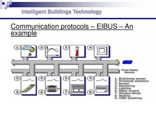
Communication protocols – EIBUS – An example
Intelligent Buildings Technology. Communication protocols – EIBUS – An example. Intelligent Buildings Technology. Communication protocols – EIBUS – Main networks The Installation Bus is designed to provide distributed technical control for management and surveillance of buildings.

Communication protocols – EIBUS – An example
E N D
Presentation Transcript
Intelligent Buildings Technology Communication protocols – EIBUS – An example
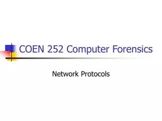
Intelligent Buildings Technology • Communication protocols – EIBUS – Main networks • The Installation Bus is designed to provide distributed technical control for management and surveillance of buildings. • Therefore it provides a serial data transmission between the devices connected to the bus. It also operates as a compatible, flexible low-cost system supporting the above applications.
Intelligent Buildings Technology • Communication protocols – EIBUS – Main networks • The Installation Bus is designed to provide distributed technical control for management and surveillance of buildings. • Therefore it provides a serial data transmission between the devices connected to the bus. It also operates as a compatible, flexible low-cost system supporting the above applications. Decentralized Centralized
Intelligent Buildings Technology Communication protocols – EIBUS
Intelligent Buildings Technology Communication protocols – EIBUS – Topology • The EIB installation bus is a twisted-pair that is laid parallel to the mains power supply network. The Bus Line interconnects all sensors and actuators of an installation together. • Sensors are command initiators such as switches and pushbuttons. Other types of sensors include temperature sensors, brightness sensors etc. Actuators are command receivers such as luminaries, blinds, heating, door openers etc. • On each Bus Line up to 64 devices can be operated. Up to 12 such Bus Lines can be joined together with a Line Coupler to form one Bus Area. Up to 15 such Bus Areas can in turn be connected by means of an Area Coupler.
Communication protocols – EIBUS – Topology EIB is a fully peer-to-peer network, which accommodates up to 65536 devices. The logical topology allows 256 devices on one line. Lines may be grouped together with a main line into an area. 15 areas together with a backbone line form an entire domain. On open media, nearby domains are logically separated with a 16-bit SystemID. Without the addresses reserved for couplers, (255 x 16) x 15 + 255 = 61.455 end devices may be joined by an EIB network. Installation restrictions may depend on implementation (medium, transceiver types, power supply capacity) and environmental (electromagnetic noise) factors. Installation and product guidelines should be taken into account.. Intelligent Buildings Technology
Intelligent Buildings Technology Communication protocols – EIBUS – Topology
Intelligent Buildings Technology Communication protocols – EIBUS – Topology
Communication protocols – EIBUS – Media Several media, like Twisted Pair, Powerline, Radio Frequency and Infrared, today support the EIB protocol. It is of course always possible to connect gateways to other media. On EIB TP (Twisted Pair), bit-level collision detection with dominant logical 0 ensures that in case of collision, the transmission always succeeds for one of the communication partners. The resulting elimination of re-transmissions further enhances the performance of EIB TP. Together with EIB's powerful group addressing, EIB TP1 Collision Avoidance caters for extreme efficiency with reaction times 100 ms for two simultaneous transmissions. Fast polling allows up to 14 devices to be polled for 1 byte status-information within 50 ms. A physical TP segment may be up to 1000 m long. The electrical segments can have an arbitrary topology (i.e. linear, star, tree, loop or combinations of them) consisting of individual wiring sections as long as the electrical requirements (resistive and capacitive length) are not exceeded. Examples of such topologies of electrical segments are shown in Figure. Intelligent Buildings Technology
Communication protocols – EIBUS – Transmission The communication between a sensor (e.g. a switch) and an actuator (e.g. a lamp) is a sequence of operations (see Fig. 3.12). In the case of the EIB protocol, a switch - being uniquely defined by its physical address - can communicate to lamps using group addressing. The group addressing is based on the exchange of data coded with common rules between communication objects (mailboxes). A communication object is only able to transmit telegram on a single group address. On the opposite side, a communication object can be subscriber to several group addresses, allowing it to receive telegram from different emitters. That means all EIB Bus devices subscribers to the right group address (i.e. our lamp) will receive the command message from the switch. Intelligent Buildings Technology
Intelligent Buildings Technology Communication protocols – EIBUS – Transmission
Intelligent Buildings Technology Communication protocols – EIBUS –OSI
Intelligent Buildings Technology • Communication protocols – EIBUS –Protocol • The information exchange between two devices is achieved by transmission of data packets. • Each data packet must be acknowledged. For every medium, the message frame is similar to: Message frame
Intelligent Buildings Technology • Communication protocols – EIBUS –Protocol • Some media will precede or follow this message by some medium specific sequences, characteristic for the medium's access control or error correction mechanisms. The data packet contains the following fields: • control field. • source address field. • destination address field. • length. • LSDU (Link Service Data Unit), i.e. info to be transferred. • check byte. Data packet
Intelligent Buildings Technology • Communication protocols – EIBUS – • Data management and addressing • To manage network resources (e.g. when configuring an installation), EIB uses a combination of broadcast and point-to-point communication. Via broadcast (optionally using a device's unique serial number), each device in the installation is assigned a unique Physical Address, which is used from then on for further point-to-point communication. • A connection (optionally with access authorization) may be built up, for example to download the complete 'applet' binary image of an application program. • Management of EIB Bus devices connected to the Installation Bus can be addressed using two modes: • Physical addressing (system operation) • Group addressing (normal operation).
Intelligent Buildings Technology Communication protocols – EIBUS – Data management and addressing Physical Group
Intelligent Buildings Technology • Communication protocols – EIBUS –Configuration • Configuration of the bus system is achieved using the EIB Tool Software developed by the EIBA. • The location and physical address of each bus device is entered in the architectural drawings. • When an installation is complete, a serial interface from a personal computer configures the EIB system.
Intelligent Buildings Technology • Communication protocols – EIBUS –Rehabiliation • The EIB bus is well suited to exploitation in the rehabilitation field for the following reasons: • Availability of commercial products. • Technology is open to third parties for exploitation. • Development kits are available. • Established network of training centres. • The major drawback of the EIB bus is that the technology has so far only been applied in great measure to the twisted pair medium. This implies that if an existing home is to receive an EIB bus, a certain amount of re-wiring will need to take place. However, the technology can be applied to other media and products do exist for Infrared and Power Line media. The EIBA is also carrying out development for the coaxial cable, optical fiber and radio frequency mediums.
Intelligent Buildings Technology • Communication protocols – EIBUS –Internetworking • The EIB protocol does not communicate to communicate. • The aim of communication is the interworking between sensors and actuators. • The interworking pyramid, defines the different interworking degrees. • It starts with the data format used and ends with the application functionality. • It can be compared to a mail exchange where the communication object is themailbox and the functionality the complete written order.
Intelligent Buildings Technology • Communication protocols – EIBUS – Components • EIB devices are divided into three types according to their use: • Basic components, such as power supply unit (PSU), choke, signal filter. • System components, which support the basic operation of the system such as Bus Coupling Unit (BCU), Line Coupler (LC), Phase Coupler, Repeater • EIB devices that are dedicated to applications such as sensors, actuators, IR-decoders, display panels. A Bus Coupling Unit or similar interface connects these types of devices to EIB.
Intelligent Buildings Technology Communication protocols – EIBUS – Components
Intelligent Buildings Technology • Communication protocols – EIBUS – Components • The definition of the various parts are: • Power Supply Unit (PSU): Provides power for feeding of EIB Bus devices (Safety Extra Low Voltage (SELV), 30 V DC nominal). • Choke: Provides the coupling of the Power Supply Unit to the data bus line. • Data rail: Mounted support with four tracks to distribute the bus onto DIN rail. • Data rail connector: Provides the connection between the bus cable and the data rail.
Intelligent Buildings Technology • Communication protocols – Lonworks • Local Operating Network Technology is a universal, open standard networking platform created by Echelon Corporation for networks control. • A LonWorks control network is any group of devices working together to monitor sensors, control actuators, communicate reliably using an open protocol, manage network operation, and provide local and remote access to network data. • In some ways, a LonWorks control network resembles a data network, such as a LAN (local area network). • Data networks consist of computers attached to various communications media, connected by routers, which communicate to one another using a common protocol. • Network management software allows administrators to configure and maintain their computer systems. • Control networks contain similar pieces optimized for cost, performance, size, and response characteristics of control. • They allow networked systems to extend into a class of applications that data networking technology cannot reach.
Intelligent Buildings Technology • Communication protocols – Lonworks • Like the computer industry, the control industry was, and in many cases is, creating centralized control solutions based on point-to-point wiring and hierarchical logic systems. • This meant that there is a "master" controller, like a computer or programmable logic controller, physically wired to individual control, monitoring and sensing points, or "slaves." • The net result worked, but was expensive and difficult to maintain, expand, and service. • It was also very expensive to install especially for retrofitting. • Before LonWorks control networks, most control systems required thousands of feet - even miles - of expensive wiring to connect dumb components to a custom-programmed central controller. • Expansion required costly rewiring and custom programming. The systems were vulnerable to failure of the central controllers. • LonWorks control networks improve this scenario. They allow simple expansion by merely plugging in new interoperable devices that work together, regardless of the manufacturer. The devices communicate using an open protocol, the LonTalk protocol. By distributing processing among all of the control devices, the central point of failure is eliminated. By allowing for free flow of information between devices, control is improved and new applications are enabled.
Intelligent Buildings Technology • Communication protocols – Lonworks • LonWorks technology nowadays provides a solution to the many problems of designing, building, installing, and maintaining control networks: networks that can range in size from two to 32,000 devices and can be used in everything from supermarkets to petroleum plants, from aircraft to railway cars, from fusion lasers to slot machines, from single family homes to skyscrapers. • In almost every industry today, there is a trend away from proprietary control schemes and centralized systems. Manufacturers are using open, off-the-shelf chips, operating systems, and parts to build products that feature improved reliability, flexibility, system cost, and performance. • LonWorks technology is accelerating the trend away from proprietary control schemes and centralized systems by providing interoperability, robust technology, faster development, and scale economies.
Intelligent Buildings Technology • Communication protocols – Lonworks network • A LonWorks network consists of a number of nodes communicating over a number of media using a common protocol. The main parts of the network are : • The nodes, which are intelligent devices, that "talk" via the communication protocol assuring their interoperation and interaction. • Network equipment (Router, Repeater, Gateway and PC cards, Router/Modem). • Transceivers (TP, Power lines, IR, RF, FO). • PC or microprocessor communications software (DDE or MIP). • Configuration, management, supervision and maintenance software.
Intelligent Buildings Technology Communication protocols – Lonworks network
Intelligent Buildings Technology • Communication protocols – Lonworks network
Intelligent Buildings Technology • Communication protocols – Lonworks network • The main advantages of the LonWorks network are: • It is a distributed control network. • Easier integration of different devices (sensors, actuators, controllers, etc.) from various manufacturers is achieved. • Higher performance due to peer-to-peer communications is ensured. • Reduced costs of installation and reconfiguration due to its distributed characteristics.
Intelligent Buildings Technology • Communication protocols – Lonworks protocol • The LonWorks protocol, also known as the LonTalk protocol and the ANSI/EIA 709.1 Control Networking Standard, is the heart of the LonWorks system. • The protocol provides a set of communication services that allow the application program in a device to send and receive messages from other devices over the network without needing to know the topology of the network or the names, addresses, or functions of other devices. • The LonWorks protocol can optionally provide end-to-end acknowledgement of messages, authentication of messages, and priority delivery to provide bounded transaction times. • Support for network management services allow for remote network management tools to interact with devices over the network, including reconfiguration of network addresses and parameters, downloading of application programs, reporting of network problems, and start/stop/reset of device application programs.
Intelligent Buildings Technology Communication protocols – Lonworks protocol
Intelligent Buildings Technology • Communication protocols – Lonworks protocol – OSI • The LonWorks protocol is a layered, packetbased, peer-to-peer communications protocol. Like the related Ethernet and Internet protocols, it is a published standard and adheres to the layered architectural guidelines of the International Standards Organization (ISO) Open Systems Interconnect (ISO OSI) reference model. • The LonWorks protocol, however, is designed for the specific requirements of control systems, rather than data processing systems. To ensure that these requirements are met with a reliable and robust communications standard, the LonWorks protocol is layered as recommended by the International Standards Organization. • By tailoring the protocol for control at each of the OSI layers, the LonWorks protocol provides a control-specific solution that provides the reliability, performance, and robust communications required for control applications.
Intelligent Buildings Technology • Communication protocols – Lonworks protocol – Channel • A channel is a specific physical communication medium (such as twisted pair or power line) to which a group of LonWorks devices are attached by transceivers specific to that channel. • Each type of channel has different characteristics in terms of maximum number of attached devices, communication bit rate, and physical distance limits.
Intelligent Buildings Technology • Communication protocols – Lonworks protocol – Addressing • The addressing algorithm defines how packets are routed from a source device to one or more destination devices. • Packets can be addressed to a single device, to any group of devices, or to all devices. • To support networks with two devices to tens of thousands of devices, the LonWorks protocol supports several types of addresses, from simple physical addresses to addresses that designate collections of many devices.
Intelligent Buildings Technology • Communication protocols – Lonworks protocol – Addressing • Physical Address. Every LonWorks device includes a unique 48-bit identifier called the Neuron ID. The Neuron ID is typically assigned when as device is manufactured, and does not change during the lifetime of the device. • Device Address. A LonWorks device is assigned a device address when it is installed into a particular network. Device addresses are used instead of physical addresses because they support more efficient routing of messages, and they simplify replacing failed devices. A network installation tool that maintains a database of the device addresses for the network assigns the device addresses. Device addresses consist of three components: a domain ID, subnet ID, and node ID. Devices must be in the same domain to exchange packets. There may be up to 32,385 devices in a domain. The subnet ID identifies a collection of up to 127 devices that are on a single channel, or a set of channels connected by repeaters. Subnet IDs are used to support efficient routing of packets in large networks. There may be up to 255 subnets in a domain. The node ID identifies an individual device within a subnet.
Intelligent Buildings Technology • Communication protocols – Lonworks protocol – Addressing • Group Address. A group is a logical collection of devices within a domain. Unlike a subnet, however, devices are grouped together without regard for their physical location in the domain. There may be any number of devices in a group when unacknowledged messaging is used; groups are limited to 64 devices if acknowledged messaging is used. Groups are an efficient way to optimize network bandwidth for packets addressed to multiple devices. There may be up to 256 groups in a domain. • Broadcast Address. A broadcast address identifies all devices with a subnet, or all devices within a domain. Broadcast addresses are an efficient method to communicate with many devices, and are sometimes used instead of group addresses to conserve the limited number of available group addresses.
Intelligent Buildings Technology • Communication protocols – Lonworks protocol – Delivering • The LonWorks protocol offers three basic types of message delivery service and also supports authenticated messages. An optimized network will often use all of these services. These services allow tradeoffs between reliability, efficiency, and security, and are listed below: • Acknowledged Messaging. Provides for end-to-end acknowledgement. When using acknowledged messaging, a message is sent to a device or group of up to 64 devices and individual acknowledgements are expected from each receiver. If acknowledgements are not received, the sender times out and retries the transaction. The number of retries and the timeout are both configurable. • Repeated Messaging. Causes a message to be sent to a device or group of any number of devices multiple times. This service is typically used instead of acknowledged messaging because it does not incur the overhead and delay of waiting for acknowledgements. This is especially important when broadcasting information to a large group of devices, as an acknowledged message would cause all the receiving devices to try to transmit a response at the same time. • Unacknowledged Messaging. Causes each message to be sent once to a device or group of any number of devices and no response is expected. This messaging service has the lowest overhead and is the most typically used service. • Authenticated Service. Allows the receiver of a message to determine if the sender is authorized to send that message. Thus, authentication prevents unauthorized access to devices and is implemented by distributing 48-bit keys to the devices at installation time.
Intelligent Buildings Technology • Communication protocols – Lonworks protocol – Variables • The LonWorks protocol implements the innovative concept of network variables. • Network variables greatly simplify the tasks of designing LonWorks application programs for interoperability with multiple vendors' products and facilitating the design of information-based, rather than command-based, control systems. • A network variable is any data item (temperature, a switch value, or an actuator position setting) that a particular device application program expects to get from other devices on the network (an input network variable) or expects to make available to other devices on the network (an output network variable). • The application program in a device does not need to know anything about where input network variables come from or where output network variables go.
Intelligent Buildings Technology • Communication protocols – Lonworks protocol – Variables • When the application program has a changed value for an output network variable it simply passes the new value to the device firmware. • Via a process that takes place during network design and installation called binding, the device firmware is configured to know the logical address of the other devices or group of devices in the network expecting that network variable, and it assembles and sends the appropriate packets to these devices. • Similarly, when the device firmware receives an updated value for an input network variable required by its application program, it passes the data to the application program. • The binding process thus creates logical connections between an output network variable in one device and an input network variable in another device or group of devices. • Connections may be thought of as "virtual wires." If one device contains a physical switch, with a corresponding output network variable called switch on/off, and another device drives a light bulb with a corresponding input network variable called lamp on/off, creating a connection by binding these two network variables has the same functional effect as connecting a physical wire from the switch to the light bulb.
Intelligent Buildings Technology • Communication protocols – Lonworks protocol – Variables • Every network variable has a type that defines the units, scaling, and structure of the data contained within the network variable. Network variables must be the same type to be connected. This prevents common installation errors from occurring such as a pressure output being connected to a temperature input. • Type translators are available to convert network variables of one type to another type. A set of standard network variable types (SNVTs) is defined for commonly used types. Alternatively, manufacturers may define their own userdefined network variable types (UNVTs). • Network variables make possible information-based control systems, rather than old-style command-based control systems. This means that in a LonWorks system, each device application makes its own control decisions, based on information it collects from other devices about what is going on in the system. • In a command-based system, devices issue control commands to other devices, so a command-issuing device, that is typically a centralized controller, must be custom programmed to know a lot about the system function and topology. • This makes it very difficult for multiple vendors to design standard control devices that can easily be integrated. Network variables make it easy for manufacturers to design devices that systems integrators can readily incorporate into interoperable, information-based control systems.
Intelligent Buildings Technology Communication protocols – Lonworks protocol – Devices
Intelligent Buildings Technology • Communication protocols – Lonworks protocol – Device • The basis of every LonWorks device is the Neuron Chip as it contains the entire required device hardware and software. The Neuron Chip contains three identical 8-bit central processing units (CPUs) that are dedicated to the following functions: • 1. CPU-1 is the media access control, which drives the communication subsystem hardware and executes the media access algorithm. CPU-1 communicates with CPU-2 using network buffers located in shared memory. CPU-1 handles layers 3 to 6. • 2. CPU-2 is the network CPU that implements layers 3 through 6 of the LonTalk protocol. It handles network variable processing, addressing, transaction processing, authentication and network management. • 3. CPU-3 is the application CPU that runs code written by the user together with the operating systems services called by the application code.
Intelligent Buildings Technology Communication protocols – Lonworks protocol – Device
Intelligent Buildings Technology Communication protocols – Lonworks protocol – Device Neuron Chip
Intelligent Buildings Technology • Communication protocols – Lonworks protocol – LonPoint • The Lon Point system is the result of such a systems approach providing the low cost of an open system architecture, the multiuser capabilities of the LNS Network Operating System, the distributed processing capabilities of the Neuron Chip and Lon-Works platform and the wiring flexibility of free topology communications. • The system consists of the LonPoint Interface, Router and Scheduler Modules, Lon-Point Application Programs, LNS-based LonMaker for Windows Integration Tool, and the LonPoint Software Plug-In. The various I/O modules of the LonPoint system are described next.
Intelligent Buildings Technology Communication protocols – Lonworks protocol – LonPoint
Intelligent Buildings Technology Communication protocols – Lonworks protocol – LonPoint
Intelligent Buildings Technology • Communication protocols – Lonworks protocol – LonMark objects • The LonMark Association is an organization aiming at enabling the easy integration of multi-vendor systems based on LonWorks networks and providing an open forum for member companies to work together on marketing and technical programs to promote the availability of open interoperable control devices. The Association is focusing on: • Promoting benefits of interoperable LonMark products. • Providing collaborative marketing programs for companies developing Lon-Mark products. • Providing a forum to define application-specific design requirements. Products that have been verified to conform to LonMark interoperability guidelines are eligible to carry the LonMark logo. The LonMark logo is an indicator that a product has completed the conformance tests and has been designed to interoperate across a LonWorks network.
Intelligent Buildings Technology • Communication protocols – Lonworks protocol – LonMark objects • As mentioned above the LonTalk protocol employs a data oriented application layer that supports the data communication rather than commands between nodes. By this approach application data such as temperatures, pressures, etc can be sent to multiple nodes, each of which may have a different application for that datum. The data in the LonTalk protocol are called the network variables and configuration properties. Standard Network Variable Types (SNVTs) and Standard Configuration Parameter Types (SCPTs) provide a common platform for representing a wide range of data by specifying units, range and resolution. • At the application layer, interoperability between LonWorks technology-based products is facilitated through the use of application-specific LonMark Objects and SNVTs. LonMark Objects build upon network variables and provide a concise application layer interface that incorporates semantic meaning about the information being communicated.
Intelligent Buildings Technology • Communication protocols – Lonworks protocol – LonMark objects • There are three types of LonMark Objects: • The Node Object, the Sensor Object and the Actuators Object. • The Sensor Object is a generic object that can be used with any form of sensor, such as analog pressure, temperature or humidity sensor or even a digital switch. The Sensor Object can supply data directly to an Actuator Object or to control loop located within a Controller Object. There are two versions of the Sensor Object: one with no feedback named the 'Open Loop Sensor Object' and the other with feedback named the 'Closed Loop Sensor Object'. • The Open Loop Sensor Object is suitable for use with sensing devices that report absolute rather than relative values and for use with devices that do not require feedback information for correct operation. • The Closed Loop Sensor Object includes a feedback feature that makes it suitable for use in applications where multiple sensors can be combined in arbitrary combinations with multiple actuators devices. The purpose of the closed loop sensor object is to enable multiple sensors to control a common actuator or a single sensor to control multiple actuators while retaining synchronization between the actual and desired states of objects in both the sensors and actuators.