
Understanding Interconnections in Computer Architecture: Buses, I/O, and OS Management
E N D
Presentation Transcript
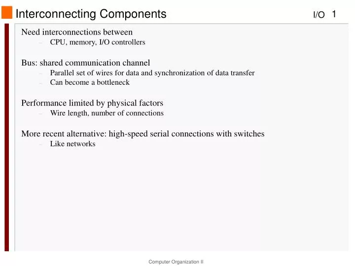
Interconnecting Components • Need interconnections between • CPU, memory, I/O controllers • Bus: shared communication channel • Parallel set of wires for data and synchronization of data transfer • Can become a bottleneck • Performance limited by physical factors • Wire length, number of connections • More recent alternative: high-speed serial connections with switches • Like networks
Bus Types • Processor-Memory buses • Short, high speed • Design is matched to memory organization • Goal: maximize processor-memory bandwidth • I/O buses • Longer, allowing multiple connections • Specified by standards for interoperability • Connect to processor-memory bus through a bridge • Connect to a wide variety of devices, with wide range in data bandwidth
Bus Signals and Synchronization • Data lines • Carry address and data • Multiplexed or separate • Control lines • Indicate data type, synchronize transactions • Synchronous • Uses a bus clock • Asynchronous • Uses request/acknowledge control lines for handshaking
Synchronous Buses • Uses a clock signal among the control lines and a fixed protocol for communication. • For example, for a memory read operation: • - transmit the address and read command on 1st clock tick • - require memory unit to respond with the requested data word on the 5th clock tick • Predetermined protocol allows, simple control logic, easily implemented as a small FSM. • Bus can run fast. • Every device on bus must run on same clock rate. • Clock skew issues limit the physical length or the speed of the bus.
Asynchronous Buses • Uses request/acknowledge control lines for "handshaking". • No clock signal is used (hence, asynchronous). • Wide variety of devices can be connected on same bus. • Bus can have greater (but not unlimited) length. • All the examples in the following table are asynchronous buses.
I/O Bus Examples FIGURE 6.8 Key characteristics of fi ve dominant I/O standards. The intended use row indicates whether it is designed to be used with cables external to the computer or just inside the computer with short cables or wire on printed circuit boards. PCIe can support simultaneous reads and writes, so some publications double the bandwidth per lane assuming a 50/50 split of read versus write band width.
Typical x86 PC I/O System FIGURE 6.9 Organization of the I/O system on an Intel server using the Intel 5000P chip set. If you assume reads and writes are each half the traffic, you can double the bandwidth per link for PCIe.
I/O Management • How is a user request transformed into a device command and communicated to the device? • How is data actually transferred to or from a memory location? • What is the role of the OS? • I/O is mediated by the OS • Multiple programs share I/O resources • Need protection and scheduling • I/O causes asynchronous interrupts • Same mechanism as exceptions • I/O programming is fiddly • OS provides abstractions to programs
Role of the OS • Guarantees that a user's program accesses only the parts of an I/O device to which the user has rights. • Provides abstractions for accessing devices by supplying routines that handle low-level device operations. • Handles interrupts generated by I/O devices. • Tries to provide "equitable" access to shared I/O resources. • Tries to schedule accesses to improve system throughput.
I/O Commands • I/O devices are managed by I/O controller hardware • Transfers data to/from device • Synchronizes operations with software • Command registers • Cause device to do something • Status registers • Indicate what the device is doing and occurrence of errors • Data registers • Write: transfer data to a device • Read: transfer data from a device
I/O Register Mapping • Memory mapped I/O • Registers are addressed in same space as memory • Address decoder distinguishes between them • OS uses address translation mechanism to make them only accessible to kernel • I/O instructions • Separate instructions to access I/O registers • Can only be executed in kernel mode • Example: x86
Polling • Processor must periodically check I/O status register • If device ready, do operation • If error, take action • Common in small or low-performance real-time embedded systems • Predictable timing • Low hardware cost • In other systems, wastes CPU time
Interrupts • When a device is ready or error occurs • Controller interrupts CPU • Interrupt is like an exception • But not synchronized to instruction execution • Can invoke handler between instructions • Interrupt-cause information often identifies the interrupting device • Priority interrupts • Devices needing more urgent attention get higher priority • Can interrupt handler for a lower priority interrupt
I/O Data Transfer • Polling and interrupt-driven I/O • CPU transfers data between memory and I/O data registers • Time consuming for high-speed devices • Direct memory access (DMA) • OS provides starting address in memory • I/O controller transfers to/from memory autonomously • Controller interrupts on completion or error
DMA/Cache Interaction • If DMA writes to a memory block that is cached • Cached copy becomes stale • If write-back cache has dirty block, and DMA reads memory block • Reads stale data • Need to ensure cache coherence • Flush blocks from cache if they will be used for DMA • Or use non-cacheable memory locations for I/O
DMA/VM Interaction • OS uses virtual addresses for memory • DMA blocks may not be contiguous in physical memory • Should DMA use virtual addresses? • Would require controller to do translation • If DMA uses physical addresses • May need to break transfers into page-sized chunks • Or chain multiple transfers • Or allocate contiguous physical pages for DMA