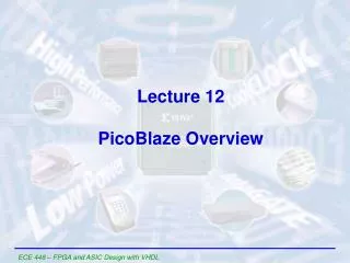
PicoBlaze CPLD Microcontroller
PicoBlaze CPLD Microcontroller. Agenda. What is PicoBlaze PicoBlaze operation PicoBlaze software flow Customize PicoBlaze Memory integration Why PicoBlaze. What is PicoBlaze?. A fully customizable 8-bit soft microcontroller macros that provides 49 16-bit instructions

PicoBlaze CPLD Microcontroller
E N D
Presentation Transcript
Agenda • What is PicoBlaze • PicoBlaze operation • PicoBlaze software flow • Customize PicoBlaze • Memory integration • Why PicoBlaze
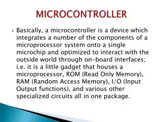
What is PicoBlaze? • A fully customizable 8-bit soft microcontroller macros that provides • 49 16-bit instructions • 8 general-purpose 8-bit registers • 256 directly and indirectly addressable ports • Reset and a maskable interrupt
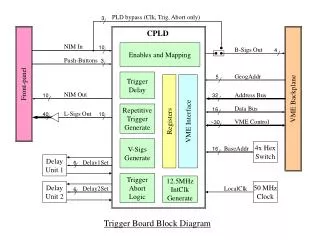
Port Address Control 8 8 8 8 IN_PORT 8 8 8 8 8 ALU Interrupt Flag Store ZERO & CARRY Flags 8 Program Counter 8 Operational Control & Instruction Decoding ADDRESS Interrupt Control Program Flow Control 8 Program Counter Stack PicoBlaze Block Diagram PORT_ID READ_STROBE WRITE_STROBE 8 Registers 8-bit OUT_PORT INTERRUPT 16 CONSTANT DATA INSTRUCTION 8 RESET CLK
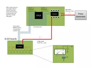
CLK ADDRESS(7:0) 00 00 01 02 03 04 0700 0700 0801 F632 DC5A RESET INSTRUCTION(15:0) PicoBlaze Operation PicoBlaze IN_PORT[7:0] OUT_PORT[7:0] PORT_ID[7:0] INTERRUPT READ_STROBE Program ROM RESET WRITE_STROBE INSTRUCTION[15:0] INSTRUCTIOIN[15:0] ADDRESS[7:0] ADDRESS[7:0] CLK CLK 2 clock cycle operation
PicoBlaze Instruction Set • Program Control Group • JUMP • CALL • RETURN • Logical Group • LOAD • AND • OR • XOR • Arithmetic Group • ADD • ADDCY • SUB • SUBCY • Shift & Rotate Group • SR0 • SR1 • SRX • SRA • RR • SL0 • SL1 • SLX • SLA • RL • Input/Output Group • INPUT • OUTPUT • Interrupt Group • RETURNI ENABLE • RETURNI DISABLE • INTERRUPT ENABLE • INTERRUPT DISABLE
Assembler • A simple DOS executable file • Written in C • Use Microsoft Visual Studio 6.0 • Easy to change
Assembler Files Filename.asm <User input file> ASM.EXE Filename.mcs <Binary code for ROM> <VHDL for simulation> Filename.vhd Filename.bin Filename.fmt Filename.log <Binary code in hex format> <Formatted assembly file> <Assembler report>
A Simple Shifter Constant shifter_port, 04 ;declare port Namereg s7, shifter_reg ;declare register Loop1: Load shifter_reg, 01 ;init shifter reg Loop2: Output shifter_reg, shifter_port SL0 shifter_reg ;shift left with 0 Jump NZ, loop2 ;goto loop2 when s7<>0 Jump loop1 ;goto loop1
Shifter Program Load s7, 01 Output s7, 04 SL0 s7 Jump NZ, 01 Jump 00
PicoBlaze Software Flow • Compile PicoBlaze source • Use WebPACK 5.2i or later • Use FISE 5.2i or later • Assemble the program code • asm filename.asm • Download to the CPLD • iMPACT 5.2i or later • Download assembled object code to EEPROM
Making a Processor Change • Add an instruction • Modify picoblaze.vhd • Add a constant with instruction code: constant new_instruction_id : std_logic_vector(4 downto 0) := “10101"; • Add instruction decoding signal i_new_instruction <= '1' when instruction(15 downto 11) = new_instruction_id else '0'; • Define VHDL component with functionality of new instruction • Add new component to picoblaze.vhd • Tweak the assembler • Add new instruction to asm.cpp char *new_instruction_id = “10101“; • Add case to write_program_word function of asm.cpp • Recompile asm.cpp to create asm.exe
Making a Processor Change • A DSP example - bit reversal (“Flip”) operation • 12 to 18 instructions needed in regular microcontroller programming • A newly created FLIP function in PicoBlaze can be used to complete the operation in just one instruction cycle
Program Memory Integration • Binary code and processor can be integrated into a single CPLD • Eliminates external PROM • SOC solution • Reduces size • Increases performance
Integration Design Flow • Assemble the design • Use PicoBlaze Assembler • asm design.asm • Generates design.vhd • Write top level VHDL • Wrap picoblaze.vhd and design.vhd (output from assembler) • Compile top level VHDL source • Use WebPACK 5.2i or later • Use FISE 5.2i or later • Download to CPLD • Use iMPACT 5.2i or later
1 + 1 < 2 PicoBlaze PicoBlaze + Shifter - Fitter removes redundant circuits
PicoBlaze Demonstration • Demonstrate simple shifter • Add FLIP instruction • Exchanges bits in specified register • MSB to LSB • LSB to MSB • Modify picoblaze.vhd • Create FLIP component • Modify asm.cpp • Demonstrate FLIP instruction with new program
Why Use PicoBlaze? • Emulate out of production processors • Lower power consumption than older small processors • Customizable for performance • PicoBlaze runs faster than most 8-bit and16-bit uCs (PICs, 8051, 6811, 80188, 6816, etc.) • Customizable for specific applications • uCs have fixed features • uCs have fixed instructions sets • PicoBlaze can run functions quickly in parallel logic
Why Use PicoBlaze? • PicoBlaze is parameterized • uCs have fixed size • uCs have limited I/Os • Can be reconfigured “On the Fly (OTF)” • Cryptography/security
Conclusion • PicoBlaze is a soft microcontroller module • Use PicoBlaze for custom microcontroller applications • Create custom instruction sets • Program memory integration • Use PicoBlaze Assembler • Compile with current Xilinx software
CoolRunner-II Reference Designs Free HDL CoolRunner-II design code download:http://www.xilinx.com/products/xaw/coolvhdlq.htm
Appendix A • Instruction set descriptions • Syntax • Bit description
Program Syntax • No blank lines – Use a semicolon for blank lines • Comments – Any item on a line following a semicolon (;) • Constant – Must be specified in the form of a 2 digit hexadecimal value(00 – FF) • Line Labels – To identify a program line for JUMP or CALL instruction should be followed by a colon (:) • CONSTANT Directive – Assigns an 8-bit constant value to a label • NAMEREG Directive – Assigns a new name to any of the 8 registers • ADDRESS Directive – Forces the following instructions commencing at a new address value
Program Control JUMP CALL RETURN Address Unconditional Conditional if Zero if NOT Zero if Carry if NOT Carry Instruction syntax
Interrupt Control Instruction syntax INTERRUPT RETURNI Don’t Care Enable Disable
Logical Operation LOAD sX, C AND sX, C OR sX, C XOR sX, C Constant Instruction syntax sY sX K sY
Arithmetic Operation ADD sX, C ADDCY sX, C SUB sX, C SUBCY sX, C Constant Instruction syntax sY sX K sY
SHIFT/ROTATE SR0/SL0 SR1/SL1 SRX/SLX SRA/SLA RR/RL Carry Instruction sX L - Left R - Right Instruction syntax
Input/Output Control Input Output Constant PORT_ID Instruction syntax sY sX P sY