Hydraulic Transients
Hydraulic Transients. When the Steady-State design fails!. gradually. varied. Hydraulic Transients: Overview. In all of our flow analysis we have assumed either _____ _____ operation or ________ ______ flow What about rapidly varied flow? How does flow from a faucet start?


Hydraulic Transients
E N D
Presentation Transcript
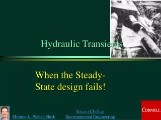
Hydraulic Transients When the Steady-State design fails!
gradually varied Hydraulic Transients: Overview • In all of our flow analysis we have assumed either _____ _____ operation or ________ ______ flow • What about rapidly varied flow? • How does flow from a faucet start? • How about flow startup in a large, long pipeline? • What happens if we suddenly stop the flow of water through a tunnel leading to a turbine? steady state
Hydraulic Transients Unsteady Pipe Flow: time varying flow and pressure • Routine transients • change in valve settings • starting or stopping of pumps • changes in power demand for turbines • changes in reservoir elevation • turbine governor ‘hunting’ • action of reciprocating pumps • lawn sprinkler • Catastrophic transients • unstable pump or turbine operation • pipe breaks
References • Chaudhry, M. H. 1987. Applied Hydraulic Transients. New York, Van Nostrand Reinhold Company. • Wylie, E. B. and V. L. Streeter. 1983. Fluid Transients. Ann Arbor, FEB Press.
Analysis of Transients • Gradually varied (“Lumped”) _________ • conduit walls are assumed rigid • fluid assumed incompressible • flow is function of _____ only • Rapidly varied (“Distributed”) _________ • fluid assumed slightly compressible • conduit walls may also be assumed to be elastic • flow is a function of time and ________ ODE time PDE location
Establishment of Flow:Final Velocity How long will it take? 1 g = 9.8 m/s2 H = 100 m K = ____ f = 0.02 L = 1000 m D = 1 m 1.5 H EGL HGL V 2 0.5 L Ken= ____ Kexit= ____ 1.0 minor major
Final Velocity g = 9.8 m/s2 H = 100 m K = 1.5 f = 0.02 L = 1000 m D = 1 m 9.55 m/s What would V be without losses? _____ 44 m/s
Establishment of Flow:Initial Velocity Navier Stokes? before head loss becomes significant 10 9 g = 9.8 m/s2 H = 100 m K = 1.5 f = 0.02 L = 1000 m D = 1 m 8 7 6 5 velocity (m/s) 4 3 2 1 0 0 5 10 15 20 25 30 time (s)
Flow Establishment:Full Solution gravity drag ________, ________
Flow Establishment:tanh! V < Vf
Time to reach final velocity Time to reach 0.9Vf increases as: L increases H decreases Head loss decreases
Flow Establishment g = 9.8 m/s2 H = 100 m K = 1.5 f = 0.02 L = 1000 m D = 1 m Was f constant? 107
Household plumbing example • Have you observed the gradual increase in flow when you turn on the faucet at a sink? • 50 psi - 350 kPa - 35 m of head • K = 10 (estimate based on significant losses in faucet) • f = 0.02 • L = 5 m (distance to larger supply pipe where velocity change is less significant) • D = 0.5” - 0.013 m • time to reach 90% of final velocity? Good! No? T0.9Vf = 0.13 s
V > Vf? If V0= Why does velocity approach final velocity so rapidly?
Lake Source Cooling Intake Schematic Motor Lake Water Surface Steel Pipe 100 m ? Plastic Pipe 3100 m Intake Pipe, with flow Q and cross sectional area Apipe 1 m Pump inlet length of intake pipeline is 3200 m Wet Pit, with plan view area Atank What happens during startup? What happens if pump is turned off?
Q Transient with varying driving force where Lake elevation - wet pit water level H = ______________________________ f(Q) What is z=f(Q)? Finite Difference Solution! Is f constant?
2 4 1.5 3 1 2 0.5 1 /s) 3 z (m) 0 0 Q (m -0.5 -1 -1 -2 -1.5 -3 -2 -4 0 200 400 600 800 1000 1200 time (s) Wet Pit Water Level and Flow Oscillations Q z constants What is happening on the vertical lines?
Wet Pit with Area Equal to Pipe Area Pipe collapse Water Column Separation Why is this unrealistic?
Period of Oscillation: Frictionless Case z = -H z = 0 at lake surface Wet pit mass balance
Period of Oscillations plan view area of wet pit (m2) 24 pipeline length (m) 3170 inner diameter of pipe (m) 1.47 gravity (m/s2) 9.81 T = 424 s Pendulum Period?
Transients • In previous example we assumed that the velocity was the same everywhere in the pipe • We did not consider compressibility of water or elasticity of the pipe • In the next example water compressibility and pipe elasticity will be central
Valve Closure in Pipeline V • Sudden valve closure at t = 0 causes change in discharge at the valve • What will make the fluid slow down?____ • Instantaneous change would require __________ • Impossible to stop all the fluid instantaneously ↑p at valve infinite force What do you think happens?
Transients: Distributed System • Tools • Conservation of mass • Conservation of momentum • Conservation of energy • We’d like to know • pressure change • rigid walls • elastic walls • propagation speed of pressure wave • time history of transient
Pressure change due to velocity change HGL steady flow unsteady flow velocity density pressure
Momentum Equation HGL 1 2 Neglect head loss! Mass conservation A1 A2 Dp = p2 - p1
Magnitude of Pressure Wave 1 2 increase Decrease in V causes a(n) _______ in HGL.
Propagation Speed:Rigid Walls Conservation of mass Solve for DV
Propagation Speed:Rigid Walls momentum mass Need a relationship between pressure and density!
Propagation Speed:Rigid Walls definition of bulk modulus of elasticity Example: Find the speed of a pressure wave in a water pipeline assuming rigid walls. (for water) speed of sound in water
Propagation Speed:Elastic Walls D Additional parameters D = diameter of pipe t = thickness of thin walled pipe E = bulk modulus of elasticity for pipe effect of water compressibility effect of pipe elasticity
Propagation Speed:Elastic Walls • Example: How long does it take for a pressure wave to travel 500 m after a rapid valve closure in a 1 m diameter, 1 cm wall thickness, steel pipeline? The initial flow velocity was 5 m/s. • E for steel is 200 GPa • What is the increase in pressure? solution
Time History of Hydraulic Transients: Function of ... • Time history of valve operation (or other control device) • Pipeline characteristics • diameter, thickness, and modulus of elasticity • length of pipeline • frictional characteristics • tend to decrease magnitude of pressure wave • Presence and location of other control devices • pressure relief valves • surge tanks • reservoirs
Time History of Hydraulic Transients 1 3 DH DH V=Vo V=0 V= -Vo V=0 a a L L 2 4 DH V=0 V= -Vo L L
Time History of Hydraulic Transients 5 7 DH DH V= -Vo V=Vo V=0 V=0 a a L L 6 8 DH V= Vo V=0 L L
Pressure variation over time DH Pressure head reservoir level Neglecting head loss! time Pressure variation at valve: velocity head and friction losses neglected Real traces
Lumped vs. Distributed lumped For _______ system • For LSC wet pit • T = 424 s • = 4*3170 m/1400 m/s = ____ pressure fluctuation period T = __________________________ 9.1 s What would it take to get a transient with a period of 9 s in Lake Source Cooling? ____________ Fast valve
Methods of Controlling Transients • Valve operation • limit operation to slow changes • if rapid shutoff is necessary consider diverting the flow and then shutting it off slowly • Surge tank • acts like a reservoir closer to the flow control point • Pressure relief valve • automatically opens and diverts some of the flow when a set pressure is exceeded
Surge Tanks • Reduces amplitude of pressure fluctuations in ________ by reflecting incoming pressure waves • Decreases cycle time of pressure wave in the penstock • Start-up/shut-down time for turbine can be reduced (better response to load changes) Reservoir Surge tank Tunnel/Pipeline Penstock tunnel T Tail water Surge tanks
Use of Hydraulic Transients • There is an old technology that used hydraulic transients to lift water from a stream to a higher elevation. The device was called a “Ram Pump”and it made a rhythmic clacking noise. • How did it work? High pressure pipe Source pipe Stream Ram Pump
Minimum valve closure time • How would you stop a pipeline full of water in the minimum time possible without bursting the pipe?
Simplify: no head loss and hold pressure constant Integrate from 0 to t and from Q to 0 (changes sign)
z3 z1 Back to Ram Pump: Pump Phase • Coordinate system? • P1 = _____ • P2 = _____ • z2-z1 = ___ 0 -z1 High pressure pipe Source pipe z Stream
Reflections • What is the initial head loss term if the pump stage begins after steady state flow has been reached? _____ • What is ?_____ • What is when V approaches zero? ______ • Where is most efficient pumping? ___________ • How do you pump the most water? ______ z1 z3 Low V (low hl) Maintain high V
Ram: Optimal Operation • What is the theoretical maximum ratio of pumped water to wasted water? • Rate of decrease in PE of wasted water equals rate of increase in PE of pumped water
High Q and Low loses? Acceleration Insignificant head loss Deceleration (pumping) Keep V high for max Q
Cycle times Change in velocities must match
Summary (exercise) When designing systems, pay attention to startup/shutdown Design systems so that high pressure waves never occur High pressure waves are reflected at reservoirs or surge tanks
Burst section of Penstock:Oigawa Power Station, Japan Chaudhry page 17
Collapsed section of Penstock:Oigawa Power Station, Japan Chaudhry page 18