SPring-8 FADC Project
SPring-8 FADC Project. 章文箴 中央研究院 物理研究所. Super Photon Ring 8 GeV (SPring-8). Harima Science Garden City. Laser Electron Photon. LEPS Detector Configuration. TPC inside LEPS Detectors. Time Projection Chamber. Working Principles of Time Projection Chamber.

SPring-8 FADC Project
E N D
Presentation Transcript
SPring-8 FADC Project 章文箴 中央研究院 物理研究所
Super Photon Ring 8 GeV (SPring-8) Harima Science Garden City
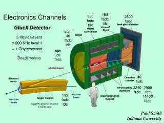
Working Principles of Time Projection Chamber • Passage of charged particles through the gas generates ionization electrons. • Electrons drift towards the readout plane along the imposed E x B drifting fields. • At the end of readout plane, an avalanche (amplification) will happen upon the arrival of electrons by the proportional sense wires and an induced image charge on the corresponding cathode pads. • The pads are connected with a read-out electronics which provides low-noise and high resolution analogue information as well as the drift time associated with the signal.
Electric Field Configuration Grid Wire Sense Wire Field Wires Cathod
TPC Mechanical Specification • Inner radius: < 1.25 cm. • Outer radius: < 30 cm. • Read out channels: 95 sensing wires, 1000 pads. • Pad size:inner 8mm*8mm, outer 8mm*13mm. • Distance between sensing wires and pads: 4mm. • Separation of sensing wire: 4mm. • Cathode readout. • Maximum drift distance : about 70 cm. • Maximum drift time: about 14 sec with drift velocity = 5.1 cm/sec.
Requirement of TPC Electronics • Good energy resolution: measuring dE/dx from the charge readout of either wires or pads for the particle identification for K/p separation at low momentum. • Requirement of spatial resolution: • x,y < 300 m. • z < 1 mm. • Position information: • x(t),y(t): x from fired sense wires; y from interpolation of signals on pads(t). • z(t) from time bin of FADC time slice. • Timing information: fitting of pulse peak in FADC. • On-board zero-suppression to ensure fast data transfer and short system dead time.
Digitizer in TPC Electronic: FADC • Large data size: • High sampling rate: 40 MHz = 25 nsec. • Read-out bit (Nbit): 10 bits. • # of Time bins per event: ~600 time bins. (Max drift time/clock = 14 sec/25 nsec = 560 bins.) • 1000 channels. • Trigger latency: 1 sec . • On-board zero-suppression. • Need of a large buffer size to store 4-5 events on board for one single VME readout.(16*600*5=48K per channel, w/o a zero suppression factor.) • High channel density.
SPring-8 FADC Module • Use TEXONO FADC and IHEP BES version as the starting point. • 40 MHz; 10-bit FADC: ADC input 0-2 V range. • Shift register inside FPGA: max length = 100 time bin. • On-board FPGA for threshold suppression. • Buffer FIFO: dual port memory. • CPLD: controlling VME actions. • Free clock running. • VME 9U; 32 channels/module; 8 detachable cards/module; 4 channel/card.
What is FPGA? • FPGA – Field-Programmable Gate ArrayIt is a logic device that • can be programmed instantly. • consists of large no. of gate patterns repeatedly fabricated on the same IC chip. • Capacity: 1,000 to 1 million gates! • Usually used with CAD tools. • Famous brand of FPGA – Xilinx, Altera:
Connection Box (C-Box) Switch Box (S-Box) Lookup table (LUT) Pads What is FPGA? (Cont’)
Lookup Tables (LUTs) • Implemented by memory • 2-bit address 4 memory entries • E.g. AND gate
Combinations of LUTs • We can realize more complex functions using more LUTs. • Another example: F= AB + C
Logic Box (LB) • Logic Box consists of a LUT, a flip-flop and MUXs to allow different signal paths. • D-FF: Common one-phase clock.
Connection Box (C-Box) • Handles connections from LB to Pads or S-Box • Well-organized switches configured by memory cells. • One we use in project:
Switch Box (S-Box) • Connects tracks from C-Boxes with each other • Each side of SB has 5 tracks. • Using same switches and memory cells as C-Box.
Your design Putting all these together … • Overall structure of the layout of the chip
Modeling Digital Systems • VHDL is for coding models of a digital system... • Reasons for modeling • requirements specification • documentation • testing using simulation • formal verification • synthesis • class assignments • Goal • most ‘reliable’ design process, with minimum cost and time • avoid design errors!
Dataflow way library ieee; use ieee.std_logic_1164.all; entity fulladd is port(A1,A2,Cin: IN std_logic; Sum, Cout: OUT std_logic); end fulladd; Architecture a of fulladd is Begin process(A1,A2,Cin) Begin Sum <= Cin XOR A1 XOR A2; Cout <= (A1 AND A2) OR (Cin AND (A1 XOR A2)); end process; end a;
SPring-8 FADC Module(4 channels, 10 bits, 40 MHz) FIFO FADC OPA FPGA
FADC Mother Board Driver CPLD Clock Driver VME Connector
Function Block RCK[4] Single Interface Write Enable RCK OE[4] Output Enable[4] Write REN[4] Data Out (16) Read Enable[4] A[4] Load 1 Single Empty FIFO[4] Load 2 Load 3 Write Enable Load 4 Horizon Data Out (16) Single Scaler Trigger a, b, e, count (10), Ecount (4) Updated Sam”pling Counts [8] Write Enable Data Out (16) Busy Time Bin Busy Single Time Bin (10) Write Enable Clock divider Data Out (16) WCK[4] Original Clk Divide 90
The block diagram of FPGA (2) in “single” module Design Block Shift register 40Mhz Clk Function Block Controller Write Data Write Enable Data Out Write Time Busy Data Count 40 MHz Data Formation Clock Count Received ADC Data Channel Count A Comparator A ≥ B ? Yes B Preseted Threshold Header, Header2, Trailer Data Format
Mixed signal AD Converter Adapter Board • 40 MHz sampling rate. • 10 bits resolution with 2Vp-p dynamic range. • Clock distribution with Phase Lock Loop circuit. • On Board digital signal delay and • Real-Time ZERO-Suppression. • High capacity First In First Out Memory. • Easy to use with high density connector.
VMEBus slave controller, with high performance BLTransfer Mode. FPGA, digital signal control chip. First In First Out memory. Differential AD Converter (40 MHz) 16 channels differential signal input connector. 32 Channels, high sampling rate Flash AD converter. Spring-8 2002/03
Lemo Connector & LED Light Clock Power On Trigger FPGA Download Reset Trigger On Busy VME Read
VME Base Address Switch (S1) Binary setting. Lowest Bit: 1. Up=off; Down=on. Current value in the plot: 0x060000.
IRQ Jumper (J4) IRQ-off IRQ-on: Connecting the two pins closest to J4. Only one module per VME crate, sitting closest to the VME repeater. The jumper on VME backplane must be on between IRQ module and VME repeater.
FADC Module Number (S2, S3) Module Number in Header2: Module Number = (S3*16+S2) Module Number above = 7
IC for BUSY Signal (U8) IC: MC10124-U8, dip16. Half-circle mark on the left.
4-channel FADC card Screw hole for fastening and ground. Potential-Meter for pedestal adjustment. Connectors for fastening to VME9U.