MULTIPURPOSE DIGITAL CDMA FM REMOTE CONTROLLER
COMMUNICATION ELECTRONICS. MULTIPURPOSE DIGITAL CDMA FM REMOTE CONTROLLER. FIRDOUS KAMAL MIZAN MIAH. EE – 513 4/19/2005. OVERVIEW. Project description - Goals and objectives Functional units Transmitter and Receiver Circuit description

MULTIPURPOSE DIGITAL CDMA FM REMOTE CONTROLLER
E N D
Presentation Transcript
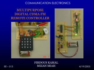
COMMUNICATION ELECTRONICS MULTIPURPOSE DIGITAL CDMA FM REMOTE CONTROLLER FIRDOUS KAMALMIZAN MIAH EE – 513 4/19/2005
OVERVIEW • Project description • - Goals and objectives • Functional units • Transmitter and Receiver • Circuit description • FSK: Modulation, Demodulation; Filters and Amplifiers • DATA encoding • PIC 16F767 mcu data processing • Time management and costs • Performance
PROJECT DESCRIPTION • House appliances such as heater, lights, oven, electrical outlets, security gates etc. do not have standard remote controllers. • Common consumer remote controllers have distance and directional limitations. • RF implementation is difficult due to noise issues and because RF bandwidth is expensive. • Security issues and cross connection between users are other concerns. • Our goal - hardware implementation of CDMA FM remote controller for household appliances.
OBJECTIVES • One transmitter and two receiver units. • Each receiver has one switch and two BCD digits. • Inputs are entered using a (4x4) keypad. • CDMA encoding is implemented for the two receivers. • FSK transmission and reception of data – Pulse length variation for high and low bit. • 8 – bit PIC16F767 microprocessor used for data encoding and decoding.
NJM 2211D – MONOLITHIC PLL CHIP FSK MODULATOR – VCO OSCILLATOR CIRCUIT DESCRIPTION: TRANSMITTER The VCO unit of the PLL can be used to generate a square wave of a desired frequency. The lock detector filter is then internally grounded with ref. Vout f0 = 1 / (R0 C0) Operating f0 designed around 100kHz Tracking bandwidth is given by: f / f0 = R0 / R1 Designed for 10% bandwidth
NON-INV AMPLIFIER (HIGH ZIN) PLL FSK DEMODULATOR 2nd ORDER ACTIVE FILTER (LOW PASS) CIRCUIT DESCRIPTION: RECEIVER • RF and CF provides a low pass data filter network. C1 and R1 provides feedback and loop damping. • For the low-pass filter: • 3dB point = 1/ 2 RC • = 160kHz • Non-inverting amplifier provides high input impedance and a closed loop gain of around 2.
Start Sequence Channel A-011100 3ms 5ms 7ms 5ms 6ms 2ms 3ms 5ms 6ms f1 f1 f1 f2 f2 2ms 2ms 2ms DATA ENCODING Pulse Width variation is used to determine a binary 1 or 0. Binary 1 is a high of 5ms followed by a low of 3ms. Binary 0 is a high of 3ms followed by a low of 3ms. Only 8 bits were retrieved by the receiver following the channel code. Thus if a bit was missed, the error could be corrected by implementing a code correcting algorithm. Furthermore, the data can be sent multiple times to reduce chances of error.
PROJECT COST • Cost estimates • Transmitter unit: $ 25 • Receiver units: $ 20 each • Total project cost: $ 85 including solder boards • Hours spent: 170 hrs (aprx) by each group member • Estimated manufacturing cost for each unit with a 20 x 4 line LCD display will be under $10 if smt or soic components are used with blow soldering on pre-printed circuit boards. • Sold for $25 will beat any commercially available unit currently on the market by more than $30 accounting for design costs by engineers. We have assumed around 10,000 units for mass production.
PERFORMANCE • All of our units were tested and demonstrated functional within the allocated time period. • We have constructed and implemented our own FSK receiver and transmitter and completed the system integration by the project demonstration date. • The units are powered by 9V batteries. • Wireless transmission is achieved for a distance of 10cm. During testing we successfully transmitted a distance of 20mm through a partex board. • On a testing trial of 50 times no errors (cross connection) between the two receiving units are observed. • The total project cost is within the proposed budget.
FURTHER IMPROVEMENTS • We down-shifted our carrier frequency from about a MHz to 100kHz to implement a frequency upconverter. • The 1MHz FSK generator implemented with a 555 timer was tested functional. • However, most high frequency components are surface mount and lacking the facilities and time, we were unable to utilize a better frequency range. • As further improvements, a higher frequency carrier will improve range (up to 50 yards with at 100MHz) with no significant increase in power. • Multiple users (receiver units) can be implemented to the current system by simply changing the channel code for each unit for the PIC mcu. • Some error bits were noticed during testing (within the same channel). This can be corrected by implementing Hamming or similar error detection/correction procedures.