ILC Baseline Configuration and Key Decisions
180 likes | 196 Vues
This document outlines the critical choices and tradeoffs made in the design of the International Linear Collider (ILC) baseline configuration, including the machine parameters, beam delivery system, and RF power systems. It also discusses alternative configurations and their implications.

ILC Baseline Configuration and Key Decisions
E N D
Presentation Transcript
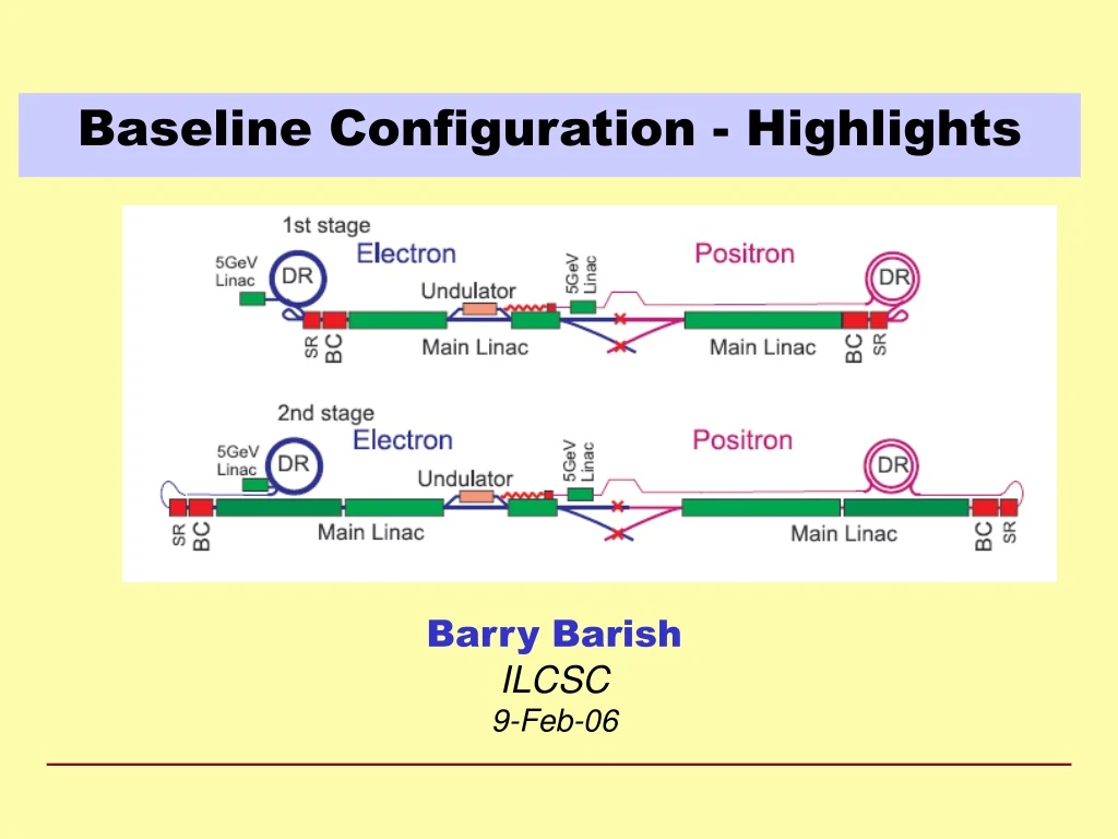
Baseline Configuration - Highlights Barry Barish ILCSC 9-Feb-06
The Key Decisions Critical choices: luminosity parameters & gradient ILCSC
Making Choices – The Tradeoffs Many decisions are interrelated and require input from several WG/GG groups ILCSC
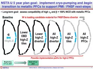
The Baseline Machine (500GeV) ~30 km ML ~10km (G = 31.5MV/m) 20mr RTML ~1.6km 2mr BDS 5km e+ undulator @ 150 GeV (~1.2km) x2 R = 955m E = 5 GeV not to scale ILCSC
Parametric Approach • A working space - optimize machine for cost/performance ILCSC
Positron-style room-temperature accelerating section E=70-100 MeV laser standard ILC SCRF modules diagnostics section sub-harmonic bunchers + solenoids Electron Source • DC Guns incorporating photocathode illuminated by a Ti: Sapphire drive laser. • Long electron microbunches (~2 ns) are bunched in a bunching section • Accelerated in a room temperature linac to about 100 MeV and SRF linac to 5 GeV. ILCSC
Primary e- source Beam Delivery System IP 250 GeV e- DR Positron Linac 150 GeV 100 GeV Helical Undulator In By-Pass Line Photon Collimators e+ DR Target e- Dump Photon Beam Dump Photon Target Adiabatic Matching Device e+ pre-accelerator ~5GeV Auxiliary e- Source Positron Source • Helical Undulator Based Positron Source with Keep Alive System Keep Alive: This source would have all bunches filled to 10% of nominal intensity. ILCSC
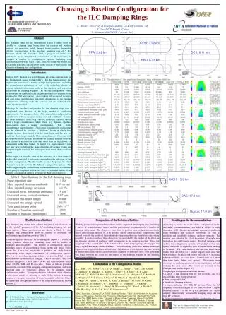
ILC Small Damping Ring Multi-Bunch Trains with inter-train gaps ILCSC
ILC Damping Ring: Baseline Design • Positrons: • Two rings of ~6 km circumference in a single tunnel. • Two rings are needed to reduce e-cloud effects unless significant progress can be made with mitigation techniques. • Preferred to 17 km dogbone due to: • Space-charge effects • Acceptance • Tunnel layout (commissioning time, stray fields) • Electrons: • One 6 km ring. ILCSC
Main Linac: SRF Cavity Gradient Total length of one 500 GeV linac 20km * assuming 75% fill factor ILCSC
Cavity: R&D • Material R&D: Fine, Large, Single Crystal • Fabrication • A number of minor modifications and improvements could be implemented without impact to the basic cavity design. • Cavity Preparation • Buffer Chemical Processing • Cavity Processing (strong R&D needed) • Electro-polishing (EP) System • High Pressure Rinsing (HPR) • Assembly Procedure ILCSC
Superconducting RF Cavities High Gradient Accelerator 35 MV/meter -- 40 km linear collider ILCSC
Improved ProcessingElectropolishing Chemical Polish Electro Polish ILCSC
RF Power: Modulator Baseline Alternate Operation: an array of capacitors is charged in parallel, discharged in series. (~2m)Will test full prototype in 2006 The Bouncer Compensated Pulse Transformer Style Modulator ILCSC
RF Power: Baseline Klystrons Specification: 10MW MBK 1.5ms pulse 65% efficiency Thales CPI Toshiba ILCSC
Increase diameter beyond X-FEL Increase diameter beyond X-FEL Review 2-phase pipe size and effect of slope ILC Cryomodule ILCSC
ILC Beam Delivery System • Baseline (supported, at the moment, by GDE exec) • two BDSs, 20/2mrad, 2 detectors, 2 longitudinally separated IR halls • Alternative 1 • two BDSs, 20/2mrad, 2 detectors in single IR hall @ Z=0 • Alternative 2 • single IR/BDS, collider hall long enough for two push-pull detectors ILCSC
Conclusions -- BCD • The baseline configuration for the ILC has been established and is document in the BCD (a 700+ page electronic document) • We have put the BCD under configuration control and are evolving it now in a controlled manner • The BCD also defines alternatives and the combination of the baseline and alternative will give good guidance for the ILC R&D program • The BCD is now being used as the starting point and basis for the reference design / cost effort this year. ILCSC