Signal Modulation and Encoding Techniques
ITP 700 Wireless Communications in Korea. Signal Modulation and Encoding Techniques. Chapter 6. Analog modulator. Information source and input transducer. Audio, video. Channel. Analog demodulator. Output transducer. Output audio, video. Overview of Analog Communication System.

Signal Modulation and Encoding Techniques
E N D
Presentation Transcript
ITP 700 Wireless Communications in Korea Signal Modulation and Encoding Techniques Chapter 6
Analog modulator Information source and input transducer Audio, video Channel Analog demodulator Output transducer Output audio, video Overview of Analog Communication System
Source Encoding • Compression of digital data to eliminate redundant information • Source coding is like quantization because its goal is to reduce bit rate • Source coding is unlike quantization because it doesnot introduce distortion
Channel Encoding • Provides protection against transmission errors by selectively inserting redundant data • Note that quantizer and source encoder work to squeeze out redundant information. The channel encoder inserts redundant information in a very selective manner
Digital Modulator/Analog Modulator • Converts digital data to a continuous waveform suitable for transmission over channel, usually a sinusoidal wave • Information is transmitted by varying one or more parameters of waveform: - Amplitude, Phase or Frequency • Linear modulation(PSK, QAM), and nonlinear (exponential) modulation(FSK)
Reasons for Choosing Modulation Techniques • Digital data, digital signal • Equipment less complex and expensive than digital-to-analog modulation equipment • Analog data, digital signal • Permits use of modern digital transmission and switching equipment
Reasons for Choosing Modulation Techniques • Digital data, analog signal • Some transmission media will only propagate analog signals • E.g., optical fiber and unguided media • Analog data, analog signal • Analog data in electrical form can be transmitted easily and cheaply • Done with voice transmission over voice-grade lines
Signal Modulation Criteria • What determines how successful a receiver will be in interpreting an incoming signal? • Signal-to-noise ratio • Data rate • Bandwidth • An increase in data rate increases bit error rate • An increase in SNR decreases bit error rate • An increase in bandwidth allows an increase in data rate
Factors Used to CompareModulation Schemes • Signal spectrum • With lack of high-frequency components, less bandwidth required • With no dc component, ac coupling via transformer possible • Transfer function of a channel is worse near band edges • Clocking • Ease of determining beginning and end of each bit position
Factors Used to CompareModulation Schemes • Signal interference and noise immunity • Performance in the presence of noise • Cost and complexity • The higher the signal rate to achieve a given data rate, the greater the cost
Basic Digital Modulation Techniques • Digital data to analog signal • Amplitude-shift keying (ASK) • Amplitude difference of carrier frequency • Frequency-shift keying (FSK) • Frequency difference near carrier frequency • Phase-shift keying (PSK) • Phase of carrier signal shifted
Signal Constellation Diagram Convenient tool to represent properties for many digital modulation schemes in 2 dimensional coordinates. Signal amplitudes in X-Y coordinates = Signal magnitude and phase in polar coordinate Relative location of signal points is important for reception => Probability of signal error dependent on the distance.
Interpretation of Signal Constellation Diagram • Axis are labeled with x(t) and y(t) • In-phase/quadrature or real/imaginary • Possible signals are plotted as points • Symbol amplitude is proportional to distance • from origin • Probability of mistaking one signal for another is • related to the distance between signal points • Decisions are made on the received signal based • on the distance of the received signal (in the I/Q plane) • to the signal points in the constellation
Amplitude-Shift Keying • One binary digit represented by presence of carrier, at constant amplitude • Other binary digit represented by absence of carrier • where the carrier signal is Acos(2πfct)
Constellation diagram for BASK y-axis A 0 x-axis 1 A 0 0
Amplitude-Shift Keying • Susceptible to sudden gain changes • Inefficient modulation technique • On voice-grade lines, used up to 1200 bps • Used to transmit digital data over optical fiber
Binary Frequency-Shift Keying (BFSK) • Two binary digits represented by two different frequencies near the carrier frequency • where f1 and f2 are offset from carrier frequency fc by equal but opposite amounts
Binary Frequency-Shift Keying (BFSK) • Less susceptible to error than ASK • On voice-grade lines, used up to 1200bps • Used for high-frequency (3 to 30 MHz) radio transmission • Can be used at higher frequencies on LANs that use coaxial cable
Multiple Frequency-Shift Keying (MFSK) • More than two frequencies are used • More bandwidth efficient but more susceptible to error • f i= f c+ (2i – 1 – M)f d • f c= the carrier frequency • f d= the difference frequency • M = number of different signal elements = 2 L • L = number of bits per signal element
Multiple Frequency-Shift Keying (MFSK) • To match data rate of input bit stream, each output signal element is held for: Ts=LT seconds • where T is the bit period (data rate = 1/T) • So, one signal element encodes L bits
Multiple Frequency-Shift Keying (MFSK) • Total bandwidth required 2Mfd • Minimum frequency separation required 2fd=1/Ts • Therefore, modulator requires a bandwidth of Wd=2L/LT=M/Ts
Phase-Shift Keying (PSK) • Two-level PSK (BPSK) • Uses two phases to represent binary digits
Phase-Shift Keying (PSK) • Differential PSK (DPSK) • Phase shift with reference to previous bit • Binary 0 – signal burst of same phase as previous signal burst • Binary 1 – signal burst of opposite phase to previous signal burst
Phase-Shift Keying (PSK) • Four-level PSK (QPSK) • Each element represents more than one bit
Phase-Shift Keying (PSK) • Multilevel PSK • Using multiple phase angles with each angle having more than one amplitude, multiple signals elements can be achieved • D = modulation rate, baud • R = data rate, bps • M = number of different signal elements = 2L • L = number of bits per signal element
Performance • Bandwidth of modulated signal (BT) • ASK, PSK BT=(1+r)R • FSK BT=2DF+(1+r)R • R = bit rate • 0 < r < 1; related to how signal is filtered • DF = f2-fc=fc-f1
Performance • Bandwidth of modulated signal (BT) • MPSK • MFSK • L = number of bits encoded per signal element • M = number of different signal elements
Quadrature Amplitude Modulation • QAM is a combination of ASK and PSK • Two different signals sent simultaneously on the same carrier frequency
Reasons for Analog Modulation • Modulation of digital signals • When only analog transmission facilities are available, digital to analog conversion required • Modulation of analog signals • A higher frequency may be needed for effective transmission • Modulation permits frequency division multiplexing
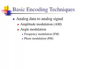
Basic Analog Modulation Techniques • Analog data to analog signal • Amplitude modulation (AM) • Angle modulation • Frequency modulation (FM) • Phase modulation (PM)
Amplitude Modulation • Amplitude Modulation • cos2fct = carrier • x(t) = input signal • na = modulation index • Ratio of amplitude of input signal to carrier • a.k.a double sideband transmitted carrier (DSBTC)
Amplitude Modulation • Transmitted power • Pt = total transmitted power in s(t) • Pc = transmitted power in carrier
Single Sideband (SSB) • Variant of AM is single sideband (SSB) • Sends only one sideband • Eliminates other sideband and carrier • Advantages • Only half the bandwidth is required • Less power is required • Disadvantages • Suppressed carrier can’t be used for synchronization purposes
Angle Modulation • Angle modulation • Phase modulation • Phase is proportional to modulating signal • np = phase modulation index
Angle Modulation • Frequency modulation • Derivative of the phase is proportional to modulating signal • nf = frequency modulation index
( ) modulated ( ) modulated
Angle Modulation • Compared to AM, FM and PM result in a signal whose bandwidth: • is also centered at fc • but has a magnitude that is much different • Angle modulation includes cos( (t)) which produces a wide range of frequencies • Thus, FM and PM require greater bandwidth than AM
Angle Modulation • Carson’s rule where • The formula for FM becomes
Basic Source Encoding Techniques • Analog data to digital signal • Pulse code modulation (PCM) • Delta modulation (DM)
Analog Data to Digital Signal • Once analog data have been converted to digital signals, the digital data: • can be transmitted using NRZ-L • can be encoded as a digital signal using a code other than NRZ-L • can be converted to an analog signal, using previously discussed techniques