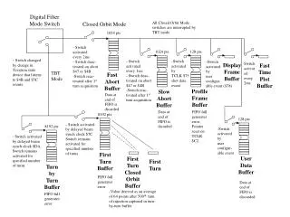
FILTER Digital
FILTER Digital. Khairul handono. Frequency Translate. Digital Filter. 512 Point FFT. x(n). X(f). Frequency Translate. Digital Filter. 1024 Point FFT. X(f). Dedicated hardware processor. Data Select. Filter Select. Data Select. FFT Select. Data Select. Data Buffers.


FILTER Digital
E N D
Presentation Transcript
FILTER Digital Khairul handono
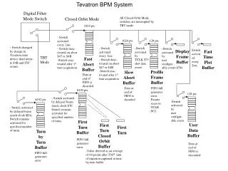
Frequency Translate Digital Filter 512 Point FFT x(n) X(f) Frequency Translate Digital Filter 1024 Point FFT X(f) Dedicated hardware processor Data Select Filter Select Data Select FFT Select Data Select Data Buffers Digital Filter Data Buffers FFT Data Buffers x(n) X(f) Micro programmable signal processor hardware
Programmable Signal Controller Data Storage x(n) Programmable S P Input/ Output X(f) Distributed Programmable Data Storage Data Storage x(n) Input/ Output X(f) Data Communication Controller x(n) Input/ Output X(f) Processing element Processing element
In the process of measuring the signal, some information is lost.
The high frequency signal is sampled just under twice every cycle
The Impulse respons of the reconstruction filter has a clasic : sin (x)/ x shape
An analogue signal which is held on the rising edge of a clock signal
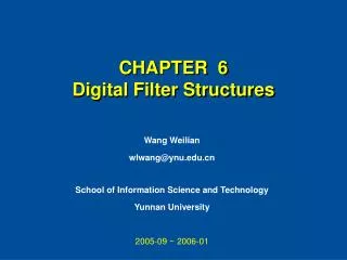
Sistematika Disain Transformasi Z Analisis Diskrit Finite Regst DSP Linier Sistem Diskrit Infinite Impulse Respons Digital Filter Finite Impulse Respons Digital Filter Multirate DSP FFT DFT Adaptive Filter Disain Digital signal
Methodology System Design Step 1 User/customer driven Develop system level Signal processing Non signal processing System level documentation Requirement specification Interface design specification System Requirements Defiition Step 2 Signal Analysis Step 3 Define input signal Types Parameter Noise sources & distribution Data rates Sisgnal Processing Design Step 4 Resource Analysis Dev SP graphs for each procss Specify primitive operation Initial partitioning Arithmetic analysis Iterative process Results in architecture approach Acceptable No Yes Step 5 Configuration Analysis Final partitioning of process Memory, Control, bandwidth Acceptable Perform resource analysis Configuration HW No Yes
Infinite Impulse Response (IIR) Disain prosedure: • Menggunakan formula disain untuk analog yaitu penentuan pole dan zero pada Butterworth, Chebyshev dan Elliptic • Formula transformasi bidang frekuensi • Transformasi bilinier, dg pemetaan pole pada bidang-s ke pole bidang-z
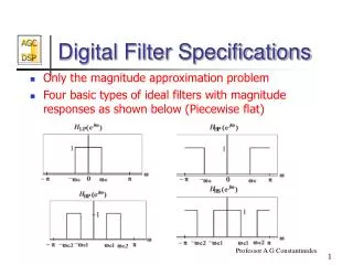
HPF LPF BSF BPF
Keuntungan Digital Filter • Stabil thd Panas: Perubahan temperatur pada R,C dan L tidak terjadi, karena menggunakan Adders, multipliers, dan sift registers • Presisi: akurasi, stabilitas, respons frekw.dg menggunakan processor register. • Mudah Penyesuaian: dapat lebih tepat dan dapat diprogram sesuai kebutuhan • Kelipatan: dapat dilipatkan untuk mendapatkan rangkaian yang lebih efisien.
Kerugian Digital Filter • Bandwidth terbatas: dengan hasil proses sampling dari analog ke digital (A/D converter), bandwidth signal terbatas setengah dari frekuensi sampling. • Keterbatasan register: implementasi sistem waktu diskrit pada perangkat keras dengan penggunaan khusus terjadi penurunan performance, karena terbatasnya jumlah bit.
Fungsi Transfer orde-N Inverse Z-tranforms
Transformasi Band Frekuensi Design normalized analog filter of order N Perform Freq. Band Transformation analog to analog Desired Digital Filter Digitize filter Design normalized analog filter of order N Desired Digital Filter Perform Freq. Band Transformation analog to analog Digitize filter
Butterworth Low Pass Filter fp = 500 Hz fs = 750 Hz Ap = 0.1737 dB As = 40 dB Ap As fp fs
S-plane Pole dan Zero Zero Pole No. Real Imaginary Real Imaginary 1 0.00000 0.00000 - 0.1564345 0.9876885 2 0.00000 0.00000 - 0.4539906 0.8910065 3 0.00000 0.00000 - 0.7071068 0.7071067 4 0.00000 0.00000 - 0.8910066 0.4539905 5 0.00000 0.00000 - 0.9876884 0.1564344 Z-plane Pole dan Zero Zero Pole No. Real Imaginary Real Imaginary 1 -1.0000 0.00000 + 0.1370099 + 0.844767 2 -1.0000 0.00000 + 0.1092149 + 0.607474 3 -1.0000 0.00000 + 0.0931414 + 0.411143 4 -1.0000 0.00000 + 0.0841441 + 0.238471 5 -1.0000 0.00000 + 0.0800774 + 0.078200
Koefisien orde 2 Numerator Denominator Stage A1 A2 B1 B2 1 2.00000 1.00000 - 0.2740197 0.7324039 2 2.00000 1.00000 - 0.2184297 0.3809528 3 2.00000 1.00000 - 0.1862828 0.1777139 4 2.00000 1.00000 - 0.1682881 0.0639486 5 2.00000 1.00000 - 0.1601547 0.0125276 IIR NORMALIZING FACTOR : C0 = 0.00125 STAGE 1 NORMALIZING FACTOR: C1 = 0.11360 STAGE 2 NORMALIZING FACTOR: C2 = 0.25799 STAGE 3 NORMALIZING FACTOR: C3 = 0.32522 STAGE 4 NORMALIZING FACTOR: C4 = 0.36908 STAGE 5 NORMALIZING FACTOR: C5 = 0.35624