Download
1 / 52
530 likes | 697 Vues
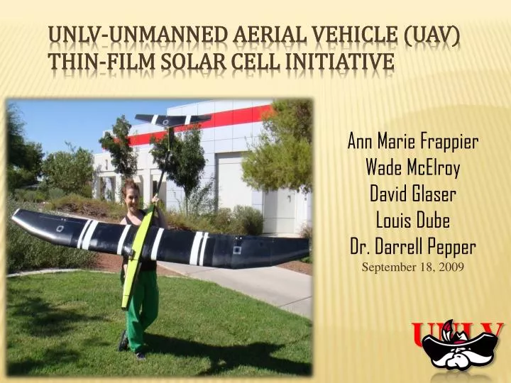
Ann Marie Frappier Wade McElroy David Glaser Louis Dube Dr. Darrell Pepper September 18, 2009. UNLV-Unmanned Aerial Vehicle (UAV) Thin-Film Solar Cell Initiative . UNLV. Project Review Final Design Airframe Optimization Component Selection Construction Questions?.

E N D
Ann Marie Frappier Wade McElroy David Glaser Louis Dube Dr. Darrell Pepper September 18, 2009 UNLV-Unmanned Aerial Vehicle (UAV) Thin-Film Solar Cell Initiative UNLV
Project Review Final Design Airframe Optimization Component Selection Construction Questions? Presentation Overview
Final design of senior design project • Project Recommendations: • Fuselage and Wing Construction • Drag Reduction • Control Surfaces • Solar Array and Charging System Starting Point
In many cases, uses less than 1% of the raw material as compared to wafer-based solar cells, resulting in significant price drop per watt So far, less efficient than wafer solar cells Printability Easily conforms to wing or fuselage surfaces Requires minimum maintenance Thin-Film Solar Cells
Amorphous silicon • The most common type of thin film cells, they are not printable. • CIS • This is a printable thin-film that attempts to drive down the cost by using copper, indium, and selenium instead of silicon. • CIGS • This is also printable and is very similar to CIS cells, the most important difference being gallium is used to replace as much of the expensive indium as possible. • CSG • Silicon offshoot that shows promise; gives up some flexibility for efficiency. Thin-Film Solar Cells
Refined mission requirements point to a maximum ceiling of 10,000ft AGL for energy height. Ability to run racetrack pattern over target for surveillance is paramount. 25° bank angle, sustained turn was chosen as appropriate for this application. The airframe must also sustain turning attitude to ride thermals. Refined Mission Requirements
Typical Mission Profile Loiter Cruise Glide Glide Climb/Thermal Climb/Thermal Climb Takeoff Land
Fuselage Design • Airfoil Design • NACA 63-806 • Preserve laminar flow • Accelerate flow into wing • Produce lift • Design Method • Airfoil • Taper after wing
Wingtip drag reduction devices • Complex airfoil and wing analysis • Fuselage-wing flow interaction • Flight behavior in different flight configurations • Ideas and calculations can be quickly and accurately modeled in COMSOL or other CFD software Airframe Optimization
Wingtip Devices • Seek to reduce drag by harnessing the strength of wingtip vortices and to either redirect them or redistribute the vortex strength (or both) • Planar or non-planar
Planar Wingtip Devices • Lays in the plane of the wing • Two different general approaches: • Employs one or more sharp edges to hamper the reconciliation of pressure gradients • Employs a recirculation seat or zone to harness the momentum or strength of the vortices, or to deflect them outside of the wing’s plane
NON-Planar Wingtip Devices • Lays outside the plane of the wing • Considered a lifting surface that has a multitude of effects on the overall aerodynamic qualities of the wing: • Impedes the circulation about the wingtip by creating a side-force (the device’s lift force), increasing overall lift • Vertically diffuses the vortex flow further away from the wingtip, decreasing overall drag • May contribute to thrust (forward lift component) • Creates an increase in wing bending moment • Must remember: winglet has its own drag component
NON-Planar Wingtip Device –WHITCOMB WINGLET
Planar Devices Wingtip Device – Planar Device 01 Wingtip Device – Planar Device 02
NON-Planar Device DESIGN PARAMETERS
WINGTIP Device NON-PLANAR DEVICES - Non-Planar Device 02 - Non-Planar Device 04
RECOMMENDATIONS • Non-Planar Device 02 showed significant improvements over entire flight envelope • Devices in general were very sensitive to changes in geometry. Most attributable to laminar separation bubble and local Reynolds number: • Investigation of various NPD’s with a specifically designed airfoil may provide even better results
Wing-Fuselage Junctions • The way the wing connects to the body of the plane • Visibly identifiable as a combination of fairing and placement on the fuselage • Junction design usually aims for a particular goal: • Reduce drag • Increase lift • Eliminate flow separation • Increase stability and control characteristics
Wing-Fuselage Junction CONTROL SPECIMEN z x y z y x
LINEAR Wing-Fuselage Junction 01 z x y z y x
NON-LINEAR Wing-Fuselage Junction 01 z x y z y x
RECOMMENDATIONS • Non-Linear Wing-Fuselage Junction 01 showed best improvement in performance although gains were minute • Results go against some of the literature but differences are easily explainable • Further design iterations with more complicated fairing shapes should be initiated
MicroUAV BTC-88 • Ball Turret System • 3.6” x 3.5” x 4.85” • 275 grams • GPS autopilot referencing • Standard servo pulse code operation • FCB-1X11A Camera • 10x optical zoom • Power consumption 6-12 VDC, 2.1 W max
FlyCamOne2 • Camera Stats • 3” x 1.5” x 0.5” • 640x480 Video • 1280x1024 Photos • Remote Activation • 2 Axis Control (Pan and Tilt) • 2.5 Hour Record Time • Thermal activated motion detector • Inexpensive alternative
Hacker A40 14L • Brushless Motor • 310 KV rating • 2.75 lbs Estimated Operating Thrust • 6 Amp/hrs • 18 x 10 Prop • Castle Creations Phoenix 80 Electric Speed Controller Propulsion System
Nominal voltage per cell: 3.7 V • 3S4P Configuration • 11.1V • 8000mAh • Possible operation at 22.2V • Lower percentage losses • Higher motor speeds • Power density 187 W/Kg Lithium Polymer Battery Array
Battery Arrangement Key Results from MotoCalc
Maximum Power Point Tracker • Stats • Panel Voltage 0-27V • Efficiency 94%-98% • Tracking Efficiency 99% • 80 grams • Benefits • Performance increase of 10-30% • Safely charge LiPo Batteries (require constant voltage)
Composite Material • Material • Carbon Fiber • Sizing • 1K • Weight • 3.74 oz/sq yrd • Weave • 5 Harness-Satin • Added flexibility over complex features
Solar Array G2- Thin Film Solar Cells P3 Portable Power Pack • Average Efficiency %10.2 • 72” x 8.25” • Vmpp: 7.3V • Impp: 5.4A • Power: 39.5W • Average Efficiency ~%7.3 • 52”x 30” • Vmpp 20V • Power 62W • Encapsulated
Construction Milestones • Airframe construction • Carbon fiber foam body • Avionics programming and testing • Avionics integration • Control surfaces • Solar array install • Wing-fuselage joining • Flight testing
CONCLUSION • Max Payload: 12-15lb • Final Cost: $5400 • Loiter Time: • Continuous Run Time: 7 hours • Hand Launch • Solar Array • CIGS Thin Film 62W Array • Investigate Silicon Cells • Construction technique • Components advances • Flight Testing