Download
1 / 26
260 likes | 461 Vues
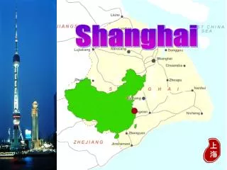
Shanghai Deep UV-FEL Control System. Control Group Ding Jianguo 2009/2/13. SDUV-FEL Control System. Introduction System Design Device control Power supply control Vacuum control Microwave control (Phase shifter, modulator…) Timing and Interlock Others. Introduction.

E N D
Shanghai Deep UV-FEL Control System Control Group Ding Jianguo 2009/2/13
SDUV-FEL Control System • Introduction • System Design • Device control • Power supply control • Vacuum control • Microwave control (Phase shifter, modulator…) • Timing and Interlock • Others
Introduction • SDUV-FEL is pre-search of chinese hard X-ray FEL • There are several FEL facilities is under construction • LCLS (Linac Coherent Light Source) • EURO-XFEL • SCSS(SPring-8 Compact SASE Source) • SDUV-FEL control system is an extended system based on 100Mev linac control system • Keep no change to those old devices which existed in 100Mev • New devices will be added in through extended cards/buses • Almost all of new devices can use the control method in SSRF • Total system can be separated to following sub systems • Injector sub-system • Linac sub-system • Undulator sub-system • Timing and interlock sub-system
System Design • SDUV-FEL control system is a distributed system based on “Standard Model” • OPI Layer • Front-end Layer • Device control Layer • Ps controller • Vacuum controller • Pump ps controller • PLC, etc. • Network/filedbuses • LAN, DeviceNet, serial, etc. • As we upgrade from the old control system, we obey the rules “use old devices as much as possible”
Archivers Loggers Consoles … Severs Firewall Operator Interface Network Front-end I/O Controllers VME bus Field bus (Ethernet) Intelligent Controllers PLCs Measurement Instruments D/I D/O A/I A/O … System Design (Architecture) Device Control
System Design (Hardware) • 1 EPICS file/data server • FTP Server • NTP Server • NFS Server • Data Archiver • Running soft IOCs • 4 OPI computers • Including original 2 Desktops • 7 IOCs • Including original 3 servers, add 4 new VME7050 • Device controller • Already 1 PLC (For vacuum interlock) • Add 2 new I/O modules • Other device controllers are maintained by other groups
System Design (Software) • OS • OPI: Scientific linux • IOC: vxWorks 5.5.1 • EPICS Server: Scientific linux • EPICS base • base 3.14.8.2 / 3.14.9 • OPI Interface • edm • Other tools • StripTool, AlarmHandler, Channel Archiver, etc.
Device Control (Magnets Power Supply) • Power supply of Injector and linac • Old power supplies are kept to be used • Some new homemade digital power supplies are added • Magnet’s power supply in undulator • Takes new homemade digital power supplies • Two types of PS, two types of interfaces in our system • DeviceNet • Ethernet
Device Control - Vacuum Monitor • Main part of injector and linac • Keep the same control method of 100Mev in injector and Linac • Add two vacuum gauges (1 Varian, 1 Pfeiffer), control in the same way as above • Udulator • 6 vacuum gauges (one leybold, others undefined) • Controlled through Ethernet
Consoles LAN IOC MVME2302 IP-Octal232 on VIPC616 RS-232 Signal converter box RS-232 VARIAN VARIAN PFEIFFER VARIAN PFEIFFER PFEIFFER Vacuum guage Device Control - Vacuum Monitor (Injector and Linac) • Epics: base-3.13.10 • O.S: vxWorks 5.3 • Device support/Driver: Support: devAscii Carrier driver:drvIpac,drvVipc616 IP driver: drvOctal Serial driver: drvSerial, drvAscii。
VME/IOC LAN Serial/Ethernet converter STP link STP link Vacuum guage 真空计 真空计 Device Control - Vacuum Monitor (Undulator) • Epics: base-3.14.8.2 • OS: vxWorks 5.5.1 • Device support/Driver • asynDriver • streamDriver
Device control – Vacuum Pump • Injector and linac • Keep old RS485 control method of 100Mev control in injector and linac • 3 new pump supplies were added and controlled through Ethernet • Undulator • 17 new pump power supplies • Controlled through Ethernet
IOC/VME GE 7050 IOC MVME2302 IP-Octal232 on VIPC616 LAN RS-232 RS-485 COM2 Serial/Ethernet box Pump ps1 Pump ps2 Pump ps14 RS485-232 IPC STP COM1 3 ion pump Injector/linac 17 ion pump (undulator) 14 ion pumps Device control – Vacuum Pump
Device Control - Valve Control • Use AB PLC-5 to control valves and implement interlock • There are 3 vacuum parts • Injector (valve V1,V2) • Linac (valve V2,V3) • Udulator (V4,V5) • When the guage value reaches alarm, relay breaks, PLC output to close valves at both ends • Comparing with old 100Mev control, 2 modules of 16 channels are added and new control logic was designed • PLC communicate with VME/IOC based on AB’s DCM protocol
IOC MVME2302 VME Remote I/O scanner Siginal converter box AB PLC-5 VARIANS LEYBOLDS PFEIFFERS OTHERS Valve controller VALVES Device Control - Valve Control Trigger interlock
Device Control - Microwave • One 2856MHz solid state amplifier’s control (Has been implemented in 100Mev) • 4 high power phase shifter, 1 power switch • 2 modulators (110MW/70MW)
Device Control – Phase Shifter • Phase shifter (including power switch control) takes DC motors, each motor include • motor direction choice • Position control • Position current read back (0-10v) • Use 100MeV Linac microwave control’s free ports • IOC controls motors’ digital/analog I/O • I/O modules’ type is VMIC 2536(32 channel DI/DO) • Vmic4514A(16 channels AI/AO)
LAN OPI/Linux VME IOC VMIC 2536 32CH DI/DO VMIC4514A 16Ch AI/AO Convert/controller (homemade) 移相器 1 移相器 2 移相器 3 移相器 4 功率 开关 固态放大器 2998MHz Device Control – Phase Shifter
Device Control – Modulator • 110MW modulator (old control system in 100Mev) • Local PLC (SLC-500) control with ladder • PLC communicates to IOC through Ethernet by 1746-DCM module • 70MW modular (newly added device) • Local Omoron PLC control • Communicate to IOC through ethernet • All control logic/interlock/execute/data acquisition are all finished by local PLC
OPI/Linux LAN IOC/VME GE 7050 IOC/VME MVME 2302 LAN AB 6008SV2R Remote IO Scanner AB SLC-500 OMRON 1746-DCM ENET-21 110MW调制器 70MW调制器 Device Control – Modulator
BNC555-2 Trigger interlock unit Timing pulse generator BNC555-1 • Output circult Fiber connection IPC/Linux --------------- OPI Timing and Interlock • Keep 100MeV design, use BNC company’s MODEL 555-8 8 channels digital pulse delay generator RF GUN联锁 调制器1组合联锁 调制器2组合连锁 反射功率保护 真空系统联锁信号 辐射防护联锁信号 热供水温联锁 备用 驱动激光器 调制器1预触发 调制器1触发 调制器2触发 微波放大器1触发 微波放大器2触发 束测系统触发 45MW功率源低电平 30MW功率源低电平 光学测量触发
Timing and Interlock - Parameters • Channels: 8 • Trigger types: Ext Trig, Ext Gate, Int, Single Shot, Burst, Duty Cycle • Repeat freq: 0.01Hz-1.0 MHz • Duty factor can be adjusted in each channel • Output pulse range: CMOS/TTL • Output pulse polarity can be choosed • Output pulse width:10ns-100s, resolution1ns • Output pulse delay:0-100s, resolution1ns • Rising edge < 5ns
Others • Network • 3 switch hubs locate on central control room, power supply room and device room, consist of local network • Video/broadcasting system • keep old system