Download
1 / 22
220 likes | 411 Vues
T.Fukui 1 , T.Hirono 2 , N.Hosoda 1 , M.Ishii 2 , M.Kitamura 1 H.Maesaka 1 ,T.Masuda 2 , T.Matsushita 2 , T.Ohata 2 , Y.Otake 1 , K.Shirasawa 1 ,M.Takeuchi 2 , R.Tanaka 2 , A.Yamashita 2 1 RIKEN Spring-8 Joint-Project for XFEL, Hyogo,679-5148, Japan 2 JASRI/SPring-8, Hyogo 679-5198, Japan.

E N D
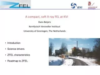
T.Fukui1, T.Hirono2, N.Hosoda1 , M.Ishii2, M.Kitamura1 H.Maesaka1,T.Masuda2, T.Matsushita2, T.Ohata2, Y.Otake1, K.Shirasawa1,M.Takeuchi2, R.Tanaka2, A.Yamashita2 1RIKEN Spring-8 Joint-Project for XFEL, Hyogo,679-5148, Japan 2JASRI/SPring-8, Hyogo 679-5198, Japan Status of the X-ray FEL control system at SPring-8
Contents • Overview of the X-ray FEL • Control System • Hardware Component • Software • Network • Project Schedule • Summary
S S S S S S S S S S S S S S S S S S S S S S S S S S S S S S S S S S S N N N N N N N N N N N N N N N N N N N N N N N N N N N N N N N N N N N N S What is X-ray FEL (XFEL) at SPring-8 • Generate brilliant coherent X-ray with wavelength of below 0.1nm • Consists of a low emittance electron gun, linear accelerator and in-vacuum undulators. • No mirror is available below 100nm Insertion Device Gun Linear Accelerator Laser Micro-bunched Random Distribution
~700m Birds-eye view of the XFEL produced with CG XFEL SPring-8 SCSS Test Acc.
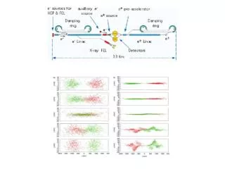
Layout of the XFEL 30MeV 50ps -> 10ps 1.45GeV 1ps -> 0.3ps (projected) 415MeV 10ps -> 1ps 0.5MeV 1μs -> 1ns 1nC 476MHz Deflector S-band (4units) L-band C-band (12units) Gun BC3 BC2 BC1 238MHz C-band Correction L-band Correction Bypass 8GeV 0.3nc 3kA peak To BL Deflector Cavity C-band (52units) Undulators(4.5m*18units) Chicane Beam dump
XFEL need ... • A machine must generate high density electron bunch with a high peak intensity and a low emittance beam. • A tolerance is very tight. • Amplitude stability < ±0.01% • 238MHz phase stability < ±0.01degree • 476MHz phase stability < ±0.02degree • C-Band Corr. timejitter < ±0.049psec 1320 - Friday October 19 Y.Otake
XFEL need ... • A machine must be very stable like a storage ring. • It is needed to suppress a temperature change of the cavity to 0.001°C. (@238MHz ~0.2°/0.01°C). • It is important to control environmental condition. • A water temperature • An air temperature and flow • A power line voltage • It must take care a facility operation as well as accelerator control.
Control System • Most of a component are same as the SCSS test accelerator. • The test accelerator is operated very well. • The control framework is similar to the SPring-8 storage ring control system. • We will take care a slow feedback by software. ( a fast feedback by hardware ) • It must be robust & scalable. • Continuous operation • More than 100 VMEs
~ 100VME & ~250PLC
Hardware Component • We use VMEbus for an equipment controller. • CPU • IA-32 + Universe(PCI-VME Bridge) with Compact Flash boot • PMC or XMC for a reflective memory • Using OPT-VME for Magnet Control • Same as the SPring-8 linac and the SCSS test accelerator.
………… I/O signals OPT-RMT ………… PLC Optical fibers VME OPT-VME FL-net(Ethernet) • We use PLC as remote I/O system • PLC for Modulator, Inverter, Vacuum, Cooling Water • We will select a optical fiber for a PLC link. • DeviceNet will be used for to reduce a wiring. • FL-net as a Communication between PLC and VME
Hardware Component • RF low level components will be installed in a water-cooled (26±0.2˚C) 19inch racks for temperature control. • IQ modulator & demodulator • High-speed A/D and D/A VME boards • Clock & trigger distribution unit • Trigger delay VME board Cooling water: 26±0.2°C Cooling air Heat Exchanger
Hardware Component • We use VME enclosure with a horizontal installation of boards • Avoid a vibration cause by the air to shake the cable. Magnet Power Supply etc. RF Low level Wiring space
Software • The MADOCA is used for the XFEL control framework. • Same as the test accelerator. • The RDBMS is a key for stable operation. • Logging data is used to find unstable parts. • LINUX as a operating system for a operator console. • X-Mate as a GUI builder • Purify will be used for memory corruption detection and memory leak detection. • For HP-UX, Purify help us to stable operation.
Software • Solaris 10 x86 as a operating system for a VME CPU. • It is possible to use Solaris Container. FL-net Main VME Solaris10 Vac EM RF EM Zone Optical PLC link FL-net Driver OS Vacuum Inverter Modulator
VME VME Shared memory VME Shared memory Shared memory Event driven data acquisition system PC filler DB MS VME EM AS Shared memory MS EMA-EV EVGEN signal VME Shared memory Shared memory Position Data BPM
Giga Ether Switch DB & File server Operator Consol 1000BASE-SX Timing VME Magnet,Vac & Interlock Magnet Power Supply Ref.Memory H-PCF PLC Injector : 6set BC1 S-Band : 4sets BC2 C-Band : 12sets BC2 C-Band : 52sets MS • Gigabit Ethernet is used for a backbone of network. • Each FL-net is separated by VLAN
Giga Ether Switch DB & File server Operator Consol 1000BASE-SX Timing VME Magnet,Vac & Interlock Magnet Power Supply Ref.Memory H-PCF PLC Injector : 6set BC1 S-Band : 4sets BC2 C-Band : 12sets BC2 C-Band : 52sets MS Gigabit FL-net
Project Schedule • The XFEL machine construction already started and the machine tunnel will be completed at March 2008. • ~ 150 piles GL -50m Bedrock
Project Schedule • Live Camera @ 10-Oct-2007
Project Schedule • The RF aging will start in October 2010 and the commissioning will start in February 2011. • The test accelerator is successfully operated to generate laser pulse about 30uJ/pulse • We will start to serve as a EUV-FEL users facility in next week.
Summary • Most of the component was testedat the SCSS test accelerator. • The SCSS test accelerator is successfully operated • Some of a component has to be improved. • A commissioning of the XFEL start in February 2011.