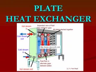
Chapter 4.3 : Compact Heat Exchangers
Chapter 4.3 : Compact Heat Exchangers. Compact heat exchangers 1) Compact heat exchangers are used when a large heat transfer surface area per unit volume is desired. This means that the smallness of weight and size is important.

Chapter 4.3 : Compact Heat Exchangers
E N D
Presentation Transcript
Compact heat exchangers 1)Compact heat exchangers are used when a large heat transfer surface area per unit volume is desired. This means that the smallness of weight and size is important. 2)Compact heat exchangers are used when at least one of the fluids is a gas. Hence the heat transfer coefficient is low 3) A heat exchanger having a surface area density greater than about 700 m2/m3 is quite referred to as a compact heat exchanger. 4)Compact heat exchangers are available in a wide variety of configurations. Many different tubular and plate configurations have been considered, where differences are due to fin design and arrangements.
Heat transfer matrices for compact heat exchangers a) Fin-tube (circular tubes, b) Plate-fin (single pass) circular fins)
c) Fin-tube (flat tubes, d) Fin-tube (circular tubes, continuous plate fins) continuous plate fins)
The heat transfer and pressure drop characteristics have been studied experimentally by Kays and London. The following figures show typical heat transfer and friction factor data for three different configurations of compact heat exchangers. Heat transfer results are correlated in terms of Colburn j factorand Reynolds numberwhere, Colburn j factor , St = Stanton number where,
Amin = minimum free-flow cross-sectional area regardless of where this minimum occurs. A = total heat transfer area. L = flow length of the heat exchanger matrix.
Heat transfer and friction factor for flow across circular tubes-continuous plate fins heat exchanger
Heat transfer and friction factor for flow across flat tubes-continuous plate fins heat exchanger
Heat transfer and friction factor for flow across circular tubes-circular fins heat exchanger
Pressure drop for plate-fin heat exchangers: 1) As the fluid enters the passage, it is subjected to pressure losses owing to sudden contraction resulting from an area change. 2) As the fluid passes through the heat exchanger matrix (i.e. core) it is subjected to pressure loss because of fluid friction. 3) Depending on whether heating or cooling occurs, a pressure change results from flow acceleration or deceleration. 4) As the fluid leaves the heat exchanger matrix, there are pressure losses associated with the area change (sudden enlargement) as well as flow separation. p = entrance effect + flow acceleration + core friction + exit effect The total pressure drop for flow of fluid across the heat exchanger matrix is given according to Kays and London by
Pressure drop for tube-fin heat exchangers: For flow normal to finned-tube banks, the contraction and expansion coefficients Kc and Ke vanish. Then, by setting Kc = Ke = 0 in the equation of pressure drop, the total pressure drop for flow across the finned-tube bank becomes p = flow acceleration + core friction
Example: Air at 1 atm and 400K and with a velocity of 10 m/s flows across a compact heat exchanger matrix of length 0.6 m and having the following configuration: a) Calculate the heat transfer coefficient. b) Find the ratio of the frictional pressure drop to the inlet pressure for the flow of air across the exchanger. Data: Tube-fin (circular tubes, continuous plate fins) heat exchanger. P =1 atm = 1.01333105 Pa , T=400 K , V = 10 m/s, L = 0.6 m
Required: h , pf Solution: For air at T = 400 K, = 0.8826 kg/m3, cp = 1014 J/kg.K, = 2.28610-5 kg/m.s, Pr = 0.689. From the figure for Tube-fin (circular tubes, continuous plate fins) heat exchanger with Re = 2627:
Then the heat transfer coefficient is The frictional pressure drop for flow across the heat exchanger matrix is determined from The ratio of the frictional pressure drop to the inlet pressure is