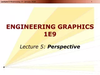
ENGINEERING GRAPHICS 1E9
Learn about Isometric Projections and Axonometric Projections, drawing methods, isometric axes, scaling, and techniques for creating accurate isometric drawings. Understand how to draw objects with various surfaces and geometries in isometric view.

ENGINEERING GRAPHICS 1E9
E N D
Presentation Transcript
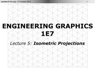
ENGINEERING GRAPHICS1E9 Lecture 3: Isometric Projections
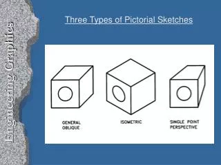
What is ISOMETRIC? • It is a method of producing pictorial view of an object showing all three faces of the object simultaneously. • It is a type of parallel projection • It is a type of axonometric projection
Axonometric Projections • Observer at infinity • Projectors parallel to each other and perpendicular to projection plane • Object is inclined with respect to projection plane
Types of Axonometric Projections Isometric Projection Dimetric Projection Trimetric Projection
Isometric Projections • All angles between axonometric axes are equal • The three coordinate axes of the object appear equally foreshortened (about 3/4th of true length) • The angles between any two of the three coordinate axes is 120°
Isometric Terminology • The three coordinate axes are called isometric axes • Any line parallel to isometric axes is called isometric line • A non-isometric line is a line not parallel to any one of the three isometric axis • In isometric projection of cube, the faces of the cube and any plane parallel to them is called isometric planes
Isometric Scale • True lengths of the edges of the object are equally foreshortened • Correct isometric projection can be drawn using an isometric scale (always smaller than ordinary scale)
Isometric Drawing Isometric Projection: Drawing prepared with isometric scale on isometric axes Isometric Drawing: Drawing prepared with ordinary scale on isometric axes
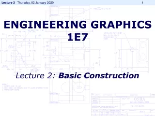
Steps: Step 1 Isometric sketches begin with defining isometric axes, three lines, one vertical and two drawn at 30° from the horizontal.
Steps: Step 2 Three lines of the isometric axes represent the three primary dimensions of the object: width, height, and depth
Steps: Step 3 Draw the font face of the isometric block.
Steps: Step 4 Draw the rest of the isometric block.
Steps: Step 5 Add details to the block starting from the front face. Then add details to the other faces.
Steps: Step 6 Darken all visible lines to complete the isometric sketch. (make sure that construction lines are light)
Axonometric projection shows all 3 dimensions, length, width and height. • The isometric lines are only drawn to scale. Objects composed entirely of isometric lines can be drawn by taking all measurements parallel to main edges of the enclosing box. • Non-isometric lines are drawn by transferring the ordinates (which are on isometric lines) of the end of the lines • Inclined and oblique surfaces are drawn using end coordinates. Box construction and offset measurements are common methods • In an isometric drawing, an angle never appears in its true size. Angles, irregular curves require special techniques
Objects with Normal Surfaces Make an Isometric Drawing with corner A at the bottom
NON-ISOMETRIC LINE Objects with Oblique Surfaces • Make an Isometric Drawing with corner A at the bottom
Objects with Non-isometric Lines • Make an Isometric Drawing with apex A facing front
Objects with Non-isometric Lines Non-isometric lines are drawn with box construction and offset measurements Non-isometric lines are not drawn in true length in isometric drawing (BA is shorter than CA in this drawing)
Irregular Objects • Make an Isometric Drawing of the following irregular object (pyramid)
Irregular Objects • OA and OB offsets help to locate apex O • Complete box construction may not be needed in each case
Objects with Circular Geometry A circle in a orthographic projection will appear as an ellipse in an isometric drawing. Instead of actual ellipses often approximate ellipses are drawn for isometric drawing. Four-centre ellipses are used to approximate ellipses on isometric planes. How to draw four-centre ellipse???
Approximate Ellipse Draw the isometric centre lines of the circle. Using the centre lines, draw an isometric square with sides equal to the diameter of the circle. From the near corners of the box, draw two large arcs with radius R, using the two red points as centres. Draw the two smaller arcs with radius r, using two green points as centres.
Objects with Non-Circular Curved Surfaces • Make an Isometric Drawing of the following curved object
Objects with Non-Circular Curved Surfaces • A line that appears as a noncircular curve in a normal orthographic view of an object appears as a non-isometricline in an isometric drawing. • Curves may be drawn using a series of points by measuring along the normal lines in the orthographic view (offset measurements) and transferring these points on isometric drawing. Accuracy increases with number of points.