Chapter 5. Multiplexing
Chapter 5. Multiplexing. Definition of Multiplexing. Transmission of information (either voice or data) from more than one source to more than one destination on the same transmission medium (facility).”

Chapter 5. Multiplexing
E N D
Presentation Transcript
Chapter 5. Multiplexing Data Communication, NUML-Islamabad
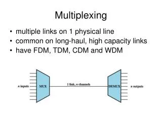
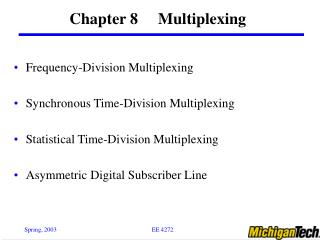
Definition of Multiplexing • Transmission of information (either voice or data) from more than one source to more than one destination on the same transmission medium (facility).” • Or multiplexing is sending of number ofseparate signals together, over the same cable or bearer, simultaneously and without interference. • TYPES: • 1) frequency division multiplexing(FDM) • 2) time division multiplexing(TDM). Data Communication, NUML-Islamabad
Audio Channel • 4-kHz Bandwidth Data Communication, NUML-Islamabad
5.2 Frequency-Division Multiplexing • SUBCARRIERS: First modulating messages onto several subcarriers and forming a composite baseband signal that consists of the sum of these modulated subcarriers, and • MAIN CARRIER: This composite signal may then be modulated onto the main carrier. • FREQUENCY ALLOCATION: In FDM, each channel of system is assigned a discrete portion of transmitted frequency. Thus many narrow bandwidth channels can be accommodated by a single wide bandwidth transmission system. Data Communication, NUML-Islamabad
fc 1 1 1 0 4 f 104 108 112 104 108 fc 2 2 0 4 f 100 104 112 100 104 fc n n 112-4n 0 4 f 108-4n 116-4n 108-4n 112-4n fc 12 12 0 4 f 60 64 68 60 64 10 11 9 8 7 12 7 4 3 2 6 1 60 108 frequency (kHz) 1 2 G1 (60-108 kHz) Basic Group Voice circuit 12 5.2.1 FDM Hierarchy • BASIC GROUP: 12-Channels- 60 to 108 kHz. Data Communication, NUML-Islamabad
1 1 0 60 108 312 360 420 480 528 312 360 fc 2 2 0 60 108 360 408 468 528 576 360 408 fc 3 3 0 60 108 408 456 516 576 624 408 456 fc 4 4 0 60 108 456 504 564 624 672 456 504 fc 5 5 0 60 108 504 552 612 672 720 504 552 1 2 3 4 5 312 360 408 456 504 552 f kHz G1 G2 G3 SG (312-552 kHz) Super Group G4 G5 60-Channel Supergroup • Combining 5 groups of 12 ch into 60-ch supergroup • Frequency range: 312 to 552 kHz Data Communication, NUML-Islamabad
SUPERGROUP CARIER FREQUENCIES 1116 1364 1612 1860 2108 2604 2852 3100 3348 3596 3844 4092 4340 2356 SG1 SG2 SG3 MASTER-GROUP 60-4028 kHz SG16 960-Channel Mastergroup 1 2 11 12 13 14 15 16 3 4 5 6 7 8 9 10 60 300 564 804 1060 1300 1556 1796 2052 2292 2548 2788 3044 3284 3540 3780 f ( kHz) 812 1052 2796 3036 312 552 1308 1548 1804 2044 2300 2540 3292 3532 3788 4028 Figure 5.2.1-3 16-supergroups assembly for 960 telephony channels Data Communication, NUML-Islamabad
12 ch/group SG1 1 G1 SG2 2 Basic Group (12 ch) G2 SG3 • Supergroup 960 ch Voice circuit G3 Mastergroup G4 12 (12 ch/group X 5 groups = 60 ch) G5 (60 ch/SG X 16 SG = 960 ch) SG16 FDM Hierarchy Figure 5.2.1-4 960-channels long-haul FDM hierarchy Data Communication, NUML-Islamabad
FDM Bandwidths • Type of baseband Bandwidth • _________ • Voice 3.4 kHz • Audio channel 4 kHz • Video 4 MHz • Television channel 6 MHz • Multiplexed voice: • 12 channels 48 kHz • 24 channels 96 kHz 36 channels 144 kHz 60 channels 240 kHz • 120 channels 480 kHz • 240 channels 960 kHz • 300 channels 1.2 MHz • 600 channels 2.4 MHz • 900 channels 3.6 MHz • 960 channels 3.84 MHz • 1,200 channels 4.80 MHz • 1,260 channels 5.04 MHz • 1,800 channels 7.20 MHz • 2,700 channels 10.8 MHz Data Communication, NUML-Islamabad
RF Carriers Radio channels: 4GHz, 6GHz 1 2 N • Number of multiplexed channels: • Maximum up to 2700 telephone channels or • television signal. RX TX Figure 5.2.1-5 Multiplexed channels for RF propagation Data Communication, NUML-Islamabad
5.3 Time-Division Multiplexing • Definition: TDM is time interleaving of samples from several sources so that information from these sources can be transmitted serially over a single communication channel. Data Communication, NUML-Islamabad
f1(t) (a) One PAM signal T f2(t) TX (a) Second PAM signal T f1(t) f2(t) (c) Two PAM signals TX T Pulse Insertion Tx:Time spacing between adjacent samples Tx= T/n n: number of input signals Data Communication, NUML-Islamabad
Ch1 t Ch2 Ch3 Ch4 Ch5 Ch6 1 2 3 4 5 61 2 3 4 5 6 1 2 3 4 5 6 Multiplexed PAM waveform Example Data Communication, NUML-Islamabad
Digital Multiplexing • Forming High-Bit-Rate Signal: Several low-bit-rate signals can be multiplexed, or combined, to form one high-bit-rate signal to be transmitted over a high-frequency medium. • Diverse Nature Signals: Signals from various incoming channels may be of such diverse nature as a digitized voice signal (PCM), computer output, telemetry data, a digital facsimile, and so on. Data Communication, NUML-Islamabad
Digital Multiplexing Techniques 1) BIT-BY-BIT Basis: Known as bit or digit interleaving 2) WORD-BY-WORD Basis: Known as byte or word interleaving). Figure 5.4-1 Digital multiplexing Data Communication, NUML-Islamabad
5.5 PCM Hierarchies – E1 System • CAPACITY: • No. of Time Slots: 32 • 1) No. of digital telephone channels: 30 of 64 kbit/s • 2) plus one for synchronization/transmission of alarms • 3) and other one for signalling. • TRANSMISSION RATE: • 32channels x 8bit/channel/125 µs =2.048 Mbit/s • (32 TS x 64 kbps = 2.0248 Mbit/s) • USAGE:E1 circuits are used to connect medium and large companies. • E3 lines are used between exchanges countries, and have transmission speed of 34.368 Mbit/s. Data Communication, NUML-Islamabad
T1 System • Multiplexes 24 digital telephone channels of 64 kbit/s into a 1.544 Mbit/s (= 64 kbps x 24 channels). • Aggregate Transmission Rate: (24channels x 8bit/channel + 1bit) / 125 µs = 1.544 Mbit/s Data Communication, NUML-Islamabad
1 frame = 125s 64 kbps PCM Frame Structure – E1 Format Time slot F 1 2 3 4 5 6 7 8 9 10 11 12 13 14 15 S 16 17 18 19 20 21 22 23 24 25 26 27 28 29 30 Channel no. Figure 5.5-1 2.048 Mbps frame structure – E1 1 2 3 4 5 6 7 8 Bit no. Data Communication, NUML-Islamabad
139.268 Mb/s Channels 2.048 Mb/s 8.448 Mb/s 34.368 Mb/s 1 1 1 2nd Order MUX (30X4=120 ch) 3rd Order MUX (120x4=480 ch) 4th Order MUX (480x4=1920 ch) 2 2 2 3 3 3 4 4 4 1 Ist Order MUX (30x1=30ch) 2 30 PCM Hierarchy Data Rates Figure 5.5.1-2 PCM hierarchies (a) E-hierarchy levels (b) T-hierarchy levels (c) E-System multiplexing hierarchy levels showing data rates Data Communication, NUML-Islamabad
2048k (30 Ch)* 8448k (120 Ch) 34 386k (480 Ch) 139 268k (1920) Ch 564 264k (7680) Ch x4 x4 x4 x4 Europe (CEPT) 32 064k (480 Ch) 97 728k (1440 Ch) 397200k (5760 Ch) x5 x3 x4 Japan 1544k (24 Ch) 6312k (96 Ch) x4 44 736k (672 Ch) North America x7 Data Communication, NUML-Islamabad