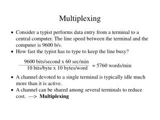
Multiplexing
Multiplexing. multiple links on 1 physical line common on long-haul, high capacity links have FDM, TDM, CDM and WDM. Frequency Division Multiplexing (FDM). FDM System Overview. FDM Voiceband Example. Analog Carrier Systems. long-distance links use an FDM hierarchy

Multiplexing
E N D
Presentation Transcript
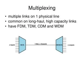
Multiplexing • multiple links on 1 physical line • common on long-haul, high capacity links • have FDM, TDM, CDM and WDM
Analog Carrier Systems • long-distance links use an FDM hierarchy • AT&T (USA) and ITU-T (International) variants • Group • 12 voice channels (4kHz each) = 48kHz • range 60kHz to 108kHz • Supergroup • FDM of 5 group signals supports 60 channels • carriers between 420kHz and 612 kHz • Mastergroup • FDM of 10 supergroups supports 600 channels • original signal can be modulated many times
TDM Link Control • no headers and trailers • data link control protocols not needed • flow control • data rate of multiplexed line is fixed • if one channel receiver can not receive data, the others must carry on • corresponding source must be quenched • leaving empty slots • error control • errors detected & handled on individual channel
Framing • no flag or SYNC chars bracketing TDM frames • must still provide synchronizing mechanism between source and destination clocks • added digit framing is most common • one control bit added to each TDM frame • identifiable bit pattern used as control channel • alternating pattern 101010…unlikely to be sustained on a data channel • receivers compare incoming bits of frame position to the expected pattern
Pulse Stuffing - problem of synchronizing various data sources - variation among clocks could cause loss of synchronization - issue of data rates from different sources not related by a simple rational number
SONET/SDH • Synchronous Optical Network (ANSI) • Synchronous Digital Hierarchy (ITU-T) • high speed capability of optical fiber • defines hierarchy of signal rates • Synchronous Transport Signal level 1 (STS-1) or Optical Carrier level 1 (OC-1) is 51.84Mbps • carries one DS-3 or multiple (DS1 DS1C DS2) plus ITU-T rates (e.g., 2.048Mbps) • multiple STS-1 combine into STS-N signal • ITU-T lowest rate is 155.52Mbps (STM-1)
Single-Server Queues with Constant Service Times and Poisson (Random) Arrivals
Cable Modems -dedicate two cable TV channels to data transfer -each channel shared by number of subscribers using statistical TDM
Cable Spectrum Division • to support both cable television programming and data channels, the cable spectrum is divided in to three ranges: • user-to-network data (upstream): 5 - 40 MHz • television delivery (downstream): 50 - 550 MHz • network to user data (downstream): 550 - 750 MHz
Asymmetrical Digital Subscriber Line (ADSL) • link between subscriber and network • uses currently installed twisted pair cable • is Asymmetric - bigger downstream than up • uses Frequency Division Multiplexing • reserve lowest 25kHz for voice (POTS) • uses echo cancellation or FDM to give two bands • has a range of up to 5.5km
Discrete Multitone (DMT) • multiple carrier signals at different frequencies • divide into 4kHz subchannels • test and use subchannels with better SNR • 256 downstream subchannels at 4kHz (60kbps) • in theory 15.36Mbps, in practice 1.5-9Mbps
Broadband – Customer Side • DSL link is between provider and customer • a splitter allows simultaneous telephone and data service • data services use a DSL modem • sometimes referred to as G.DMT modem • DSL data signal can be divided into a video stream and a data stream • the data stream connects the modem to a router which enables a customer to support a wireless local area network
Broadband – Provider Side • a splitter separates telephone from Internet • voice traffic is connected to public switched telephone network (PSTN) • data traffic connects to a DSL multiplexer (DSLAM) which multiplexes multiple customer DSL connections to a single high-speed ATM line. • ATM line connects ATM switches to a router which provides entry to the Internet
xDSL • high data rate DSL (HDSL) • 2B1Q coding on dual twisted pairs • up to 2Mbps over 3.7km • single line DSL • 2B1Q coding on single twisted pair (residential) with echo cancelling • up to 2Mbps over 3.7km • very high data rate DSL • DMT/QAM for very high data rates • separate bands for separate services
Summary • multiplexing multiple channels onsingle link • FDM • analog carrier systems • wavelength division multiplexing • TDM • TDM link control • pulse stuffing • statistical TDM • broadband • ADSL and xDSL