Multiplexing
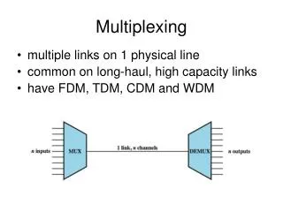
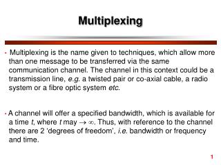
Multiplexing is a set of techniques that allows multiple signals to be transmitted simultaneously over a single communication link. Key methods include Frequency Division Multiplexing (FDM), which splits a frequency band into multiple channels, and Time Division Multiplexing (TDM), where time slots are allocated for each signal. Multiplexers combine signals for transmission, while demultiplexers decode them back into separate signals. This technology enhances the efficiency of data transmission, making it essential in modern communication systems.

Multiplexing
E N D
Presentation Transcript
Multiplexing • Multiplexing is the set of techniques that allows simultaneous transmission of multiple signals across a single link.
FDM: Frequency Division Multiplexing FDM: Frequency Division Multiplexing The division of a transmission facility into two or more channels by splitting the frequency band into narrow bands ,each of which is used to constitute a distinct channel.
Multiplexer • A device that can combine and transmit several signals over a single line
Multiplexer • In the multiplexer similar signals are modulated onto different carrier frequencies (f1,f2,f3 ) .The resulting modulated signals are then combined into a single composite single that is sent over media link that has enough bandwidth to accommodate it
DeMultiplexer • A device that decode the single line signal into multiple signals.
DeMultiplexer • The DeMultiplexer uses a series of filters to decompose the multiplexed signal into its component signals .the individual signals are then passed to a demodulator that separate them from their carriers and pass them to the waiting receivers.
Note • Link refers to the physical path . • Channel refers to the portion of a link that carries a transmission between a given pair of lines . • One link may have many channels .
Example • Assume that a voice channel occupies a bandwidth of 4 KHz. We need to combine three voice channels into a link with a bandwidth of 12 KHz, from 20 to 32 KHz. Show the configuration using the frequency domain without the use of guard bands.
Example • Five channels, each with a 100-KHz bandwidth, are to be multiplexed together. What is the minimum bandwidth of the link if there is a need for a guard band of 10 KHz between the channels to prevent interference? Ans : • For five channels, we need at least four guard bands. This means that the required bandwidth is at least 5 x 100 + 4 x 10 = 540 KHz, as shown in Figure 6.7.
WDM • WDM is designed to use the high data rate capability of fiber optic cable. • WDM is conceptually the same as FDM,except the multiplexing and demultiplexing involves optic signals transmitted through fiber optic channels.
Time division multiplexing • Time division multiplexing: is a digital process that allows several connections to share the high bandwidth of a link .Each connection occupies a portion of time in the link • TDM is a digital multiplexing technique for combining several low-rate channels into one high-rate one.
Time slots and frames • The data flow of each connection is divided into units , and the link combines one unit of each connection to make a frame. • The size of the unit can be 1 bit or several bits. • For n input connections , a frame is organized into a minimum of n time slots
Time division multiplexing • Note • In TDM , the data rate of the link that carries data from n connections must be n times the data rate of a connection to guarantee the flow of data.
Exercise • Four 1-Kbps connections are multiplexed together. A unit is 1 bit. Find (1) the duration of 1 bit before multiplexing, (2) the transmission rate of the link, (3) the duration of a time slot, and (4) the duration of a frame? Answer: • We can answer the questions as follows:1. The duration of 1 bit is 1/1 Kbps, or 0.001 s (1 ms). • 2. The rate of the link is 4 Kbps. • 3. The duration of each time slot 1/4 ms or 250 ms. • 4. The duration of a frame 1 ms.
TDM • Synchronous time division multiplexing • Statistical time division multiplexing
Synchronous time division • time slot is fixed to each device . • Data rate of medium exceeds data rate of digital signal to be transmitted • May be at bit level of blocks • Time slots pre-assigned to sources and fixed • Time slots allocated even if no data
Statistical time division Multiplexing • Multiplexer dynamically allocates time slots on demand ) • A statistical multiplexer transmits only the data from active workstations • If a workstation is not active, no space is wasted on the multiplexed stream.