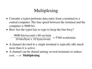
Multiplexing
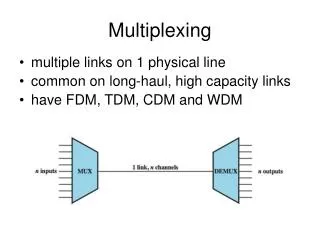
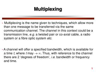
Multiplexing. Multiplexing: Combining multiple data (voice) channels for transmission on a common medium. Multiple devices sharing one physical link. Demultiplexing: Recovering the original separate channels from a multiplexed signal.


Multiplexing
E N D
Presentation Transcript
Multiplexing • Multiplexing: Combining multiple data (voice) channels for transmission on a common medium. Multiple devices sharing one physical link. • Demultiplexing: Recovering the original separate channels from a multiplexed signal. • Multiplexing and demultiplexing are performed by a multiplexer. • The two common forms of multiplexing are frequency-division multiplexing (FDM) and time-division multiplexing (TDM).
Frequency-Division Multiplexing (FDM) • Useful bandwidth of the medium exceeds the required bandwidth of the channel. • Each signal is modulated to a different carrier frequency. • Carrier frequencies are separated so signals do not overlap (guard bands). • E.g. broadcast radio, television, cable television, etc. • Channel allocated even if there is no data to be sent.
FDM System- Transmitter • Analog or digital inputs: mi(t), i = 1,n. • Each is modulated onto a subcarrier: fi. • Signals summed to produce a composite baseband: mb(t). • fichosen such that there is no overlap.
FDM System- Receiver • mb(t) is passed through n bandpass filters with response centered on fi. • Each si(t) component is demodulated to • recover the original analog/digital data.
FDM of Three Voiceband Signals • Effective spectrum of voice: 300-3400Hz. • Amplitude modulation at 64-kHz carrier: produces an 8 kHz bandwidth (60-68kHz). • For efficiency use of bandwidth, only transmit lower sideband. • Three carriers at 64, 68 and 72 kHz. • Crosstalk (overlap): use guard band to avoid. • Intermodulation noise: nonlinear effects of amplifiers in one channel can produce frequency components in other channels.
Analog Carrier Systems • Long distance voiceband signals over high-capacity links (coaxial cable, microwave). • AT&T (USA) designated a hierarchy of FDM schemes. • Group: – 12 voice channels (4kHz each) = 48kHz. – Range from 60kHz to 108kHz. Supergroup: – 60 channels. – FDM of 5 group signals on carriers between 420 kHz and 612 kHz. – Each group is treated as a separate signal with 48 kHz bandwidth. • Mastergroup: – 10 supergroups. – 600 voice channels with a bandwidth of 2.52 MHz • so original signal can be modulated many times
Example Five channels, each with a 100-KHz bandwidth, are to be multiplexed together. What is the minimum bandwidth of the link if there is a need for a guard band of 10 KHz between the channels to prevent interference? For five channels, we need at least four guard bands. This means that the required bandwidth is at least 5 x 100 + 4 x 10 = 540 KHz, as shown in the Figure.
Example Four data channels (digital), each transmitting at 1 Mbps, use a satellite channel of 1 MHz. Design an appropriate configuration using FDM The satellite channel is analog. We divide it into four channels, each channel having a 250-KHz bandwidth. Each digital channel of 1 Mbps is modulated such that each 4 bits are modulated to 1 Hz. One solution is 16-QAM modulation. The figure shows one possible configuration.
Example The Advanced Mobile Phone System (AMPS) uses two bands. The first band, 824 to 849 MHz, is used for sending; and 869 to 894 MHz is used for receiving. Each user has a bandwidth of 30 KHz in each direction. The 3-KHz voice is modulated using FM, creating 30 KHz of modulated signal. How many people can use their cellular phones simultaneously? Each band is 25 MHz. If we divide 25 MHz into 30 KHz, we get 833.33. In reality, the band is divided into 832 channels.
Wavelength Division Multiplexing • Multiple beams of light at different frequency • Carried by optical fiber • A form of FDM • Each color of light (wavelength) carries separate data channel • 1997 Bell Labs • 100 beams • Each at 10 Gbps • Giving a total 1 terabit per second (Tbps) • Commercial systems of 160 channels of 10 Gbps now available • Lab systems (Alcatel) 256 channels at 39.8 Gbps each • Total 10.1 Tbps • Over 100km
WDM Operation • Same general architecture as other FDM • Number of sources generating laser beams at different frequencies • Multiplexer consolidates sources for transmission over single fiber • Optical amplifiers amplify all wavelengths • Typically tens of km apart • Demux separates channels at the destination • Mostly 1550nm wavelength range • Was 200MHz per channel • Now 50GHz
Dense Wavelength Division Multiplexing • DWDM • No official or standard definition • Implies more channels more closely spaced that WDM • 200GHz or less
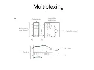
Synchronous Time-Division Multiplexing • Data rate of the medium exceeds the data rate of the digital signal to be transmitted. • Multiple digital signals interleaved in time: May be at the bit level or blocks of bytes. • Time slots preassigned to the data sources and fixed. • Time slots allocated even if no data is sent (like FDM). • Time slots do not have to be evenly distributed amongst sources.
Synchronous TDM System • Interleaving: – Can be compared to a very fast rotating switch which selects each device at a constant rate and a fixed order. – Each device sends a fixed number of bits in its timeslot. • Weakness of Synchronous TDM: fixed time slot allocations can lead to empty slots when a device has nothing to send.
TDM System • Transmitter: • Digital inputs, mi(t), i = 1,n, are briefly buffered. • Buffers are scanned sequentially to form a composite signal: mc(t). • Scanning is rapid enough so buffers are emptied before more data arrives. • Data organized into frames of one cycle. • Receiver: • Interleaved data is demultiplexed and routed to destination buffers.
TDM Link Control • no headers and trailers • data link control protocols not needed • flow control • data rate of multiplexed line is fixed • if one channel receiver can not receive data, the others must carry on • corresponding source must be quenched • leaving empty slots • error control • errors detected & handled on individual channel • Flow control and error control can be provided on a per-channel basis by using a data link control
Framing Bits • There is no flag or SYNC characters bracketing TDM frames. • Must provide a synchronising mechanism. • Most common mechanism: Added digit framing. – One control bit is added to each TDM frame: • Looks like another channel - “control channel” – Identifiable bit pattern used on the control channel. – E.g. alternating 01010101: : : which is unlikely to be sustained on a data channel. – Receiver can compare incoming bit patterns on each channel with the sync pattern. – Once synchronized, the receiver continues to monitor the control channel.
Synchronous TDM System Example • Each device sends 250 characters/second = 250*8 = 2000 bps. • Transmission is character interleaved, and each frame has one framing bit. • Therefore, the devices create 2000*4=8000 bits of data per second, and the multiplexer adds 250 bits of overhead per second.
Pulse/Bit Stuffing • It is possible to connect devices of different rates using different time slot allocations. • Since a fixed number of bits are transmitted in each time slot, each device must have a data rate which is an integer multiple of the channel rates. • For example: a device three times faster than the other devices uses three time slots. • Problem - What do we do for a device 3.75 times faster. • Solution - Pulse/Bit Stuffing: – The multiplexer adds extra dummy bits or pulses into the devices data stream to force the integer speed relationship. – Therefore the 3.75 times faster device will be raised to 4 times faster. – Stuffed bits are inserted at fixed locations in the frame and removed at the demultiplexer.
Digital Carrier Systems • Hierarchy of TDM. • USA/Canada/Japan use one system and ITU-T use a similar (but different) system. • Digital Signal (DS) Service DS-1 format: Multiplexes 24 channels. • Each frame has 8 bits per channel plus one framing bit: 8*24+1 = 193 bits per frame. • The DS service is implemented using T lines.
Digital Carrier Systems • The first bit is a framing bit, used for synchronization. • Voice channels: • 8-bit PCM used on five of six frames. • 7-bit PCM used on every sixth frame; bit 8 of each channel is a signaling bit. • Data channels: • Channel 24 is used for signaling only in some schemes. • Bits 1–7 used for 56-kbps service (8-bit data or control) • Bits 2–7 used for 9.6-, 4.8-, and 2.4-kbps service. • subrate multiplexing • additional bit is robbed from each channel to indicate which subrate multiplexing rate is being provided
SONET/SDH • SONET: Synchronous Optical Network is an optical transmission interface (proposed by BellCore and standardized by ANSI). • SDH: Synchronous Digital Hierarchy (defined by ITU-T). • Both standards are compatible and designed for the high-speed transmission capability of optical fiber. • Signal Hierarchy: – Lowest level: Synchronous Transport Signal level 1 (STS-1) or Optical Carrier level 1 (OC-1). – 51.84 Mbps. – STS-1 carries a single DS-3 or a group of lower rate signals (DS1, DS1C, DS2) plus ITU-T rates (e.g. 2.048 Mbps). – Multiple STS-1 signals combined into an STS-N signal. – ITU-T lowest rate is 155.52 Mbps (STM-1) and corresponds to SONET STS-3.
SONET Frame Format • The basic SONET building block is the STS-1 frame • STS-1 frame contains 9 rows of 90 octets = 810 octets every 125µs 51.84 Mbps.
Statistical TDM • In synchronous TDM many slots are wasted (empty slots). • Statistical or Asynchronous TDM allocates time slots dynamically based on demand. • The multiplexer scans the input lines and collects data until the frame is full. • The data rate on the multiplexed line is lower than the aggregate rates of the input lines. • may have problems during peak periods (must buffer inputs)
Statistical TDM Frame Formats • Address information is required for proper delivery of data in the frames: greater overhead. • Generally use a synchronous protocol such as HDLC. • Include one (b) or more (c) sources of data in each HDLC frame (a).
Performance • Output data rate is less than the aggregate input rates. • Anticipate the average rate of input is less than the multiplexed capacity. • May cause problems during peak periods: – Buffer inputs. - smallest possible buffer and smallest possible data rate ? – Keep buffer size to minimum to reduce delay.
Performance • I = the number of input resources • R = data rate of each source • M= effective capacity of multiplexed line (after accounting for overhead). • α = mean fraction of time each source is transmitting 0 < α <1 • K = M/IR fraction of multiplexed line capacity (compression factor, i.e K = 1 synchronous TDM) • The value of K can be bounded α< K <1
Performance • MUX as a single server queue • Total delay = time spent waiting + service time • Delay depends on the pattern of arriving traffic and the characteristics of the server. • Assume poisson arrivals and const service time • λ = α I R (λ average arrival rate) • Ts = 1/M ( Ts time it takes to transmit one bit) • The utilization of total link capacity • ρ = λ Ts = α I R/M = α /K = λ/M • Buffer size depend on ρ , and not directly on M (look at the two cases in the book) • As utilization rises, so do the buffer requirements and delay.
Performance • Data are transmitted in 1000-bit frame • Utilization is expressed as a percentage of the total line capacity. • Utilization above 80% is not desirable
Cable Modems • dedicate two cable TV channels to data transfer • each channel shared by number of subscribers, using statistical TDM • Downstream • cable scheduler delivers data in small packets • active subscribers share downstream capacity • also allocates upstream time slots to subscribers • Upstream • user requests timeslots on shared upstream channel • Headend scheduler notifies subscriber of slots to use
Asymmetrical Digital Subscriber Line (ADSL) • Modem technology designed to provide high-speed digital data transmission over ordinary telephone wire. • Link between the subscriber and the network (local exchange): Local loop. • Uses currently existing twisted pair cables: – Can carry broader spectrum than just voice bandwidth (1 MHz or more). • ADSL Design: – Asymmetric: Greater capacity downstream than upstream. – Frequency-division multiplexing: • Lowest 25kHz for voice: Plain old telephone service (POTS). • Use echo cancellation or FDM to give two bands for downstream and upstream. • Use FDM within bands each band. – Range of up to 5.5 km.