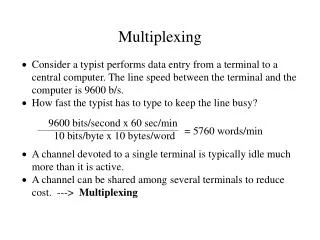
Multiplexing
Multiplexing. Many to one/one to many Types of multiplexing. The McGraw-Hill Companies, Inc., 1998. WCB/McGraw-Hill. Multiplexing. It is the set of techniques that allows the simultaneous transmission of multiple signals across a single data link.

Multiplexing
E N D
Presentation Transcript
Multiplexing • Many to one/one to many • Types of multiplexing The McGraw-Hill Companies, Inc., 1998 WCB/McGraw-Hill
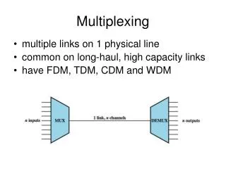
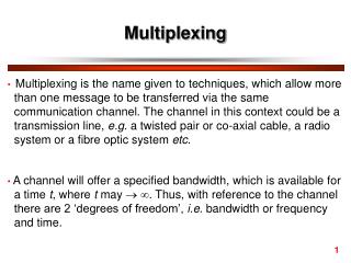
Multiplexing • It is the set of techniques that allows the simultaneous transmission of multiple signals across a single data link. • Multiplexing is done using a device called Multiplexer (MUX) that combine n input lines to generate one output line i.e. (many to one). • At the receiving end a device called Demultiplexer (DEMUX) is used that separate signal into its component signals i.e. one input and several outputs (one to many).
Advantages of Multiplexing • More than one signals can be sent over single medium or link • Effective use of the bandwidth of medium
Figure 8-1 Multiplexing vs. No Multiplexing The McGraw-Hill Companies, Inc., 1998 WCB/McGraw-Hill
Frequency Division Multiplexing • It is an analog technique. • Signals of different frequencies are combined into a composite signal and is transmitted on the single link. • Bandwidth of a link should be greater than the combined bandwidths of the various channels. • Each signal is having different frequency. • Channels are separated by the strips of unused bandwidth called Guard Bands (to prevent overlapping).
Figure 8-3 FDM The McGraw-Hill Companies, Inc., 1998 WCB/McGraw-Hill
Applications of FDM • FDM is used for FM & AM radio broadcasting. • AM frequency = 530 to 1700 kHz. • FM frequency = 88 to 108 MHz. • FDM is used in television broadcasting. • First generation cellular telephone also uses FDM.
Wave Division Multiplexing • WDM is an analog multiplexing technique. • Working is same as FDM. • In WDM different signals are optical or light signals that are transmitted through optical fiber. • Various light waves from different sources are combined to form a composite light signal that is transmitted across the channel to the receiver. • At the receiver side, this composite light signal is broken into different light waves by Demultiplexer. • This Combining and the Splitting of light waves is done by using a PRISM. • Prism bends beam of light based on the angle of incidence and the frequency of light wave.
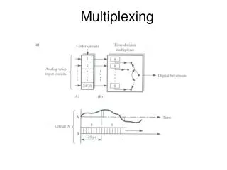
Time Division Multiplexing • It is the digital multiplexing technique. • Channel/Link is not divided on the basis of frequency but on the basis of time. • Total time available in the channel is divided between several users. • Each user is allotted a particular time interval called time slot or slice. • In TDM the data rate capacity of the transmission medium should be greater than the data rate required by sending of receiving devices.
Figure 8-8 TDM The McGraw-Hill Companies, Inc., 1998 WCB/McGraw-Hill
Types of TDM • Synchronous TDM • Asynchronous TDM
Synchronous TDM • Each device is given same Time Slot to transmit the data over the link, whether the device has any data to transmit or not. • Each device places its data onto the link when its TimeSlot arrives, each device is given the possession of line turn by turn. • If any device does not have data to send then its time slot remains empty. • Time slots are organized into Frames and each frame consists of one or more time slots. • If there are n sending devices there will be n slots in frame.
Figure 8-9 Synchronous TDM The McGraw-Hill Companies, Inc., 1998 WCB/McGraw-Hill
Multiplexing Process in STDM • In STDM every device is given opportunity to transmit a specific amount of data onto the link. • Each device gets its turn in fixed order and for fixed amount of time = INTERLEAVING. • Interleaving is done by a character (one byte). • Each frame consist of four slots as there are four input devices. • Slots of some devices go empty if they do not have any data to send.
Figure 8-10 TDM, Multiplexing The McGraw-Hill Companies, Inc., 1998 WCB/McGraw-Hill
Figure 8-11 TDM, Demultiplexing The McGraw-Hill Companies, Inc., 1998 WCB/McGraw-Hill
Disadvantages of STDM • The channel capacity cannot be fully utilized. Some of the slots go empty in certain frames.
Figure 8-14 Asynchronous TDM The McGraw-Hill Companies, Inc., 1998 WCB/McGraw-Hill
Asynchronous TDM • Also known as Statistical Time Division multiplexing. • In this time slots are not Fixed i.e. slots are Flexible. • Total speed of the input lines can be greater than the capacity of the path. • Slots are not predefined rather slots are allocated to any of the device that has data to send.
Figure 8-15 Frames and Addresses a. Only three lines sending data The McGraw-Hill Companies, Inc., 1998 WCB/McGraw-Hill
Figure 8-15-continued Frames and Addresses b. Only four lines sending data The McGraw-Hill Companies, Inc., 1998 WCB/McGraw-Hill
Figure 8-15-continued Frames and Addresses c. All five lines sending data The McGraw-Hill Companies, Inc., 1998 WCB/McGraw-Hill