System Design
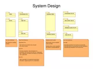
System Design. Why is Design so Difficult?. Analysis: Focuses on the application domain Design: Focuses on the solution domain Design knowledge is a moving target The reasons for design decisions are changing very rapidly Halftime knowledge in software engineering: About 3-5 years

System Design
E N D
Presentation Transcript
Why is Design so Difficult? • Analysis: Focuses on the application domain • Design: Focuses on the solution domain • Design knowledge is a moving target • The reasons for design decisions are changing very rapidly • Halftime knowledge in software engineering: About 3-5 years • What I teach today will be out of date in 3 years • Cost of hardware rapidly sinking • “Design window”: • Time in which design decisions have to be made • Technique • Time-boxed prototyping
The Purpose of System Design Problem • Bridging the gap between desired and existing system in a manageable way • Use Divide and Conquer • We model the new system to be developed as a set of subsystems New System Existing System
Overview System Design I (Chapter 6) 0. Overview of System Design 1. Design Goals 2. Subsystem Decomposition System Design II: Addressing Design Goals (Chapter 7) 3. Concurrency 4. Hardware/Software Mapping 5. Persistent Data Management 6. Global Resource Handling and Access Control 7. Software Control 8. Boundary Conditions
How to use the results from the Requirements Analysis for System Design • Nonfunctional requirements => • Activity 1: Design Goals Definition • Functional model => • Activity 2: System decomposition (Selection of subsystems based on functional requirements, cohesion, and coupling) • Object model => • Activity 4: Hardware/software mapping • Activity 5: Persistent data management • Dynamic model => • Activity 3: Concurrency • Activity 6: Global resource handling • Activity 7: Software control • Subsystem Decomposition • Activity 8: Boundary conditions
Identifying Design Goals • Prioritize criteria • Performance • Response time, throughput, memory • Dependability • Robustness, reliability, availability, fault tolerance, security, safety • Cost • Cost of development, deployment, upgrading, maintenance, administration • Maintenance • Extensibility, modifiability, adaptability, portability, readability, traceability of requirements • End user • Utility, usability • Tradeoffs are decided at this point
Typical Design Trade-offs • Functionality vs. Usability • Cost vs. Robustness • Efficiency vs. Portability • Rapid development vs. Functionality • Cost vs. Reusability • Backward Compatibility vs. Readability
Nonfunctional Requirements may give a clue for the use of Design Patterns • Read the problem statement again • Use textual clues (similar to Abbot’s technique in Analysis) to identify design patterns • Text: “manufacturer independent”, “device independent”, “must support a family of products” • Abstract Factory Pattern • Text: “must interface with an existing object” • Adapter Pattern • Text: “must deal with the interface to several systems, some of them to be developed in the future”, “ an early prototype must be demonstrated” • Bridge Pattern
Textual Clues in Nonfunctional Requirements • Text: “complex structure”, “must have variable depth and width” • Composite Pattern • Text: “must interface to an set of existing objects” • Façade Pattern • Text: “must be location transparent” • Proxy Pattern • Text: “must be extensible”, “must be scalable” • Observer Pattern • Text: “must provide a policy independent from the mechanism” • Strategy Pattern
System Design Concepts • Subsystems and services • Services and subsystem interfaces • Coupling and cohesion • Layers and partitions • Architectural styles
Subsystems and Services • Subsystem (UML: Package) • Collection of classes, associations, operations, events and constraints that are interrelated • Seed for subsystems: UML Objects and Classes. • (Subsystem) Service: • Group of operations provided by the subsystem • Seed for services: Subsystem use cases • Service is specified by Subsystem interface: • Specifies interaction and information flow from/to subsystem boundaries, but not inside the subsystem. • Should be well-defined and small. • Often called API: Application programmer’s interface, but this term should used during implementation, not during System Design
Services and Subsystem Interfaces • Service: A set of related operations that share a common purpose • Notification subsystem service: • LookupChannel() • SubscribeToChannel() • SendNotice() • UnscubscribeFromChannel() • Services are defined in System Design • Subsystem Interface: Set of fully typed related operations. • Subsystem Interfaces are defined in Object Design • Also called application programmer interface (API)
Identifying Subsystems • Heuristics • Assign objects identified in one use case into the same subsystem • Create a dedicated subsystem for objects used for moving data among subsystems • Minimize the number of associations crossing subsystem boundaries • All objects in the same subsystem should be functionally related
Coupling and Cohesion • Goal: Reduction of complexity while change occurs • Cohesion measures the dependence among classes • High cohesion: The classes in the subsystem perform similar tasks and are related to each other (via associations) • Low cohesion: Lots of miscellaneous and auxiliary classes, no associations • Coupling measures dependencies between subsystems • High coupling: Changes to one subsystem will have high impact on the other subsystem (change of model, massive recompilation, etc.) • Low coupling: A change in one subsystem does not affect any other subsystem • Subsystems should have as maximum cohesion and minimum coupling as possible: • How can we achieve high cohesion? • How can we achieve loose coupling?
Example of reducing the coupling of subsystems. Alternative 1: Direct access to the Database subsystem ResourceManagement IncidentManagement MapManagement Database
Example of reducing the coupling of subsystems (continued) Alternative 2: Indirect access to the Database through a Storage subsystem ResourceManagement IncidentManagement MapManagement Storage Database
Choosing Subsystems • Criteria for subsystem selection: Most of the interaction should be within subsystems, rather than across subsystem boundaries (High cohesion). • Does one subsystem always call the other for the service? • Which of the subsystems call each other for service? • Primary Question: • What kind of service is provided by the subsystems (subsystem interface)? • Secondary Question: • Can the subsystems be hierarchically ordered (layers)? • What kind of model is good for describing layers and partitions?
Partitions and Layers • Partitioning and layering are techniques to achieve low coupling. • A large system is usually decomposed into subsystems using both, layers and partitions. • Partitions vertically divide a system into several independent (or weakly-coupled) subsystems that provide services on the same level of abstraction. • A layer is a subsystem that provides subsystem services to a higher layers (level of abstraction) • A layer can only depend on lower layers • A layer has no knowledge of higher layers
Relationships between Subsystems • Layer relationship • Layer A “Calls” Layer B (runtime) • Layer A “Depends on” Layer B (“make” dependency, compile time) • Partition relationship • The subsystem have mutual but not deep knowledge about each other • Partition A “Calls” partition B and partition B “Calls” partition A
C1 C1 C1 C1 C1 C1 C1 C1 C1 VM1 attr attr attr attr attr attr attr attr attr op op op op op op op op op VM2 VM3 VM4 Closed Architecture (Opaque Layering) • Any layer can only invoke operations from the immediate layer below • Design goal: High maintainability, flexibility
C1 C1 C1 C1 C1 C1 C1 C1 C1 attr attr attr attr attr attr attr attr attr op op op op op op op op op Open Architecture (Transparent Layering) • Any layer can invoke operations from any layers below • Design goal: Runtime efficiency VM1 VM2 VM3 VM4
Properties of Layered Systems • Layered systems are hierarchical. They are desirable because hierarchy reduces complexity (by low coupling). • Closed architectures are more portable. • Open architectures are more efficient. • If a subsystem is a layer, it is often called a virtual machine. • Layered systems often have a chicken-and egg problem • Example: Debugger opening the symbol table when the file system needs to be debugged
Example of a Layered System Layer Application • ISO’s OSI Reference Model • ISO = International Standard Organization • OSI = Open System Interconnection • Reference model defines 7 layers of network protocols and strict methods of communication between the layers. • Closed software architecture Presentation Session Level of abstraction Transport Network DataLink Physical
OSI model Packages and their Responsibility • The Physical layer represents the hardware interface to the net-work. It allows to send() and receivebits over a channel. • The Datalink layerallows to send and receive frames without error using the services from the Physical layer. • The Network layer is responsible for that the data are reliably transmitted and routed within a network. • The Transport layeris responsible for reliably transmitting from end to end. (This is the interface seen by Unix programmers when transmitting over TCP/IP sockets) • The Session layer is responsible for initializing a connection, including authentication. • The Presentation layer performs data transformation services, such as byte swapping and encryption • The Application layer is the system you are designing (unless you build a protocol stack). The application layer is often layered itself.
Application Swing AWT Xlib An example of open architecture: Java Swing
Software Architecture • Subsystem decomposition • Identification of subsystems, services, and their relationship to each other. • Specification of the system decomposition is critical. • Software architecture • Defines the system in terms of subsystems and interactions among those subsystems • Shows correspondence between requirements and elements of the constructed system • Addresses system-level non-functional requirements
Software Architectural Styles • Software architectural style • How subsystems and their interactions are organized in order to meet certain design goals while delivering the required services • Some styles • Repository • Client/Server • Peer-To-Peer • Model/View/Controller • Pipes and Filters
Repository Subsystem createData() setData() getData() searchData() Repository Architectural Style • Subsystems access and modify data from a single data structure • Subsystems are loosely coupled (interact only through the repository) • Control flow is dictated by central repository (triggers) or by the subsystems (locks, synchronization primitives)
SemanticAnalyzer Repository SymbolTable ParseTree SourceLevelDebugger Examples of Repository Architectural Style Compiler • Database Management Systems • Modern Compilers SyntacticAnalyzer Optimizer CodeGenerator LexicalAnalyzer SyntacticEditor
Client/Server Architectural Style • One or many servers provides services to instances of subsystems, called clients. • Client calls on the server, which performs some service and returns the result • Client knows the interface of the server (its service) • Server does not need to know the interface of the client • Response in general immediately • Users interact only with the client
Client/Server Architectural Style • Often used in database systems: • Front-end: User application (client) • Back end: Database access and manipulation (server) • Functions performed by client: • Customized user interface • Front-end processing of data • Initiation of server remote procedure calls • Access to database server across the network • Functions performed by the database server: • Centralized data management • Data integrity and database consistency • Database security • Concurrent operations (multiple user access) • Centralized processing (for example archiving)
Design Goals for Client/Server Systems • Service Portability • Server can be installed on a variety of machines and operating systems and functions in a variety of networking environments • Transparency, Location-Transparency • The server might itself be distributed (why?), but should provide a single "logical" service to the user • Performance • Client should be customized for interactive display-intensive tasks • Server should provide CPU-intensive operations • Scalability • Server should have spare capacity to handle larger number of clients • Flexibility • The system should be usable for a variety of user interfaces and end devices (eg. WAP Handy, wearable computer, desktop) • Reliability • System should survive node or communication link problems
Problems with Client/Server Architectural Styles • Client/server systems do not provide peer-to-peer communication • Peer-to-peer communication is often needed • Example: Database receives queries from application but also sends notifications to application when data have changed
Peer-to-Peer Architectural Style • Generalization of Client/Server Architecture • Clients can be servers and servers can be clients • More difficult because of possibility of deadlocks
initiator Controller 1 repository * Model 1 notifier subscriber View * Model/View/Controller • Subsystems are classified into 3 different types • Model subsystem: Responsible for application domain knowledge • View subsystem: Responsible for displaying application domain objects to the user • Controller subsystem: Responsible for sequence of interactions with the user and notifying views of changes in the model. • MVC is a special case of a repository architecture: • Model subsystem implements the central datastructure, the Controller subsystem explicitly dictate the control flow
Example of a File System Based on the MVC Architectural Style
2.User types new filename 3. Request name change in model :Controller 1. Views subscribe to event :Model 5. Updated views 4. Notify subscribers :InfoView :FolderView Sequence of Events (Collaborations)
% ps auxwww | grep dutoit | sort | more dutoit 19737 0.2 1.6 1908 1500 pts/6 O 15:24:36 0:00 -tcsh dutoit 19858 0.2 0.7 816 580 pts/6 S 15:38:46 0:00 grep dutoit dutoit 19859 0.2 0.6 812 540 pts/6 O 15:38:47 0:00 sort ps grep sort more UNIX Shell: Pipe and filter architectural style • Most suited for • Applications with sequential processing of data • Minimal need for user interaction
Summary • System Design • Reduces the gap between requirements and the (virtual) machine • Decomposes the overall system into manageable parts • Design Goals Definition • Describes and prioritizes the qualities that are important for the system • Defines the value system against which options are evaluated • Subsystem Decomposition • Results into a set of loosely dependent parts which make up the system