Pipelining
Pipelining. By Pradondet Nilagupta Based on Lecture note on Advanced Computer Architecture Prof. Mike Schulte Prof. Yirng-An Chen. A. B. C. D. Introduction to Pipelining. Pipelining: An implementation technique that overlaps the execution of multiple instructions. Laundry Example


Pipelining
E N D
Presentation Transcript
Pipelining By Pradondet Nilagupta Based on Lecture note on Advanced Computer Architecture Prof. Mike Schulte Prof. Yirng-An Chen
A B C D Introduction to Pipelining • Pipelining: An implementation technique that overlaps the execution of multiple instructions. • Laundry Example • Ann, Brian, Cathy, Dave each have one load of clothes to wash, dry, and fold • Washer takes 30 minutes • Dryer takes 40 minutes • “Folder” takes 20 minutes
A B C D Sequential Laundry 6 PM Midnight 7 8 9 11 10 Time • Sequential laundry takes 6 hours for 4 loads • If they learned pipelining, how long would laundry take? 30 40 20 30 40 20 30 40 20 30 40 20 T a s k O r d e r
30 40 40 40 40 20 A B C D Pipelined LaundryStart work ASAP 6 PM Midnight 7 8 9 11 10 • Pipelined laundry takes 3.5 hours for 4 loads • Speedup = 6/3.5 = 1.7 Time T a s k O r d e r
30 40 40 40 40 20 A B C D Pipelining Lessons 6 PM 7 8 9 • Pipelining doesn’t help latency of single task, it helps throughput of entire workload • Pipeline rate limited by slowest pipeline stage • Multiple tasks operating simultaneously • Potential speedup = Number pipe stages • Unbalanced lengths of pipe stages reduces speedup • Time to “fill” pipeline and time to “drain” it reduces speedup Time T a s k O r d e r
Computer Pipelines • Execute billions of instructions, so throughput is what matters • RISC desirable features: all instructions same length, registers located in same place in instruction format, memory operands only in loads or stores
30ns 3ns Comb. Logic R E G Clock Pipelining Basics Unpipelined System • One operation must complete before next can begin • Operations spaced 33ns apart Delay = 33ns Throughput = 30MHz Op1 Op2 Op3 ?? Time
10ns 3ns 10ns 3ns 10ns 3ns Comb. Logic R E G Comb. Logic R E G Comb. Logic R E G Clock 3 Stage Pipelining • Space operations 13ns apart • 3 operations occur simultaneously Delay = 39ns Throughput = 77MHz Op1 Op2 Op3 Op4 ?? Time
5ns 3ns 15ns 3ns 10ns 3ns Com. Log. R E G Comb. Logic R E G Comb. Logic R E G Limitation: Nonuniform Pipelining • Throughput limited by slowest stage • Delay determined by clock period * number of stages • Must attempt to balance stages Delay = 18 * 3 = 54 ns Throughput = 55MHz Clock
5ns 3ns 5ns 3ns 5ns 3ns 5ns 3ns 5ns 3ns 5ns 3ns Com. Log. R E G Com. Log. R E G Com. Log. R E G Com. Log. R E G Com. Log. R E G Com. Log. R E G Clock Limitation: Deep Pipelines • Diminishing returns as add more pipeline stages • Register delays become limiting factor • Increased latency • Small throughput gains Delay = 48ns, Throughput = 128MHz
Limitation: Sequential Dependencies Comb. Logic R E G Comb. Logic R E G Comb. Logic R E G • Op4 gets result from Op1 ! • Pipeline Hazard Clock Op1 Op2 Op3 Op4 ?? Time
4 3 5 3 4 2 6 Pipeline registers Speed Up Equation for Pipelining • Assumptions: • No delays except component’s latencies • A fixed pipeline overhead: 2ns. • What is the cycle time for the pipeline version of the circuit that maximizes performance without allocating multiple cycles to a stage? • What is the total execution time for the pipeline version? • What is the speedup versus a single-cycle unpipelined version?
Multiple-Cycle DLX: Cycles 1 and 2 • Most DLX instruction can be implemented in 5 clock cycles (see Figure 3.1 on page 130). • The first two clock cycles are the same for every instruction. 1. Instruction fectch cycle (IF) IR <= Mem[PC] (load instruction) NPC <= PC+4 (update program counter) 2. Instruction decode / register fetch cycle (ID) A <= Regs[IR ] (fetch source reg1) B <= Regs[IR ] (fetch source reg2) Imm <= (IR ) ## IR (fetch and sign-ext imm.) 6...10 11…15 16 16 16…31
Multiple-Cycle DLX: Cycle 3 • The third cycle is known as the Execution/ effective address cycle (EX) • The actions performed in this cycle depend on the type of operations. • Memory reference (e.g., LW R1, 30 (R2)) ALUOutput <= A + Imm (Calculate effective address) • Register-Register ALU op. (e.g., ADD R1, R2, R3) ALUOutput <=A op B (Perform ALU operation) • Register-Immed. ALU op. (e.g., ADDI R1, R2, #3) ALUOutput <=A op Imm (Perform ALU operation) • Branch (e.g., BEQZ R4, next) ALUOutput <= NPC + Imm (Compute branch target) Cond <= (A == 0) (Compare A to 0)
Multiple-Cycle DLX: Cycle 4 • The fourth cycle is known as the Memory access / branch completion cycle (MEM) • The only DLX instructions active in this cycle are loads, stores, and branches • Loads (e.g., LW R1, 30 (R2)) LMD <= Mem[ALUOutput] (load memory onto processor) • Stores (e.g., 500(R4), R3) Mem[ALUOutput] <= B (store data into memory) • Branch (e.g., BEQZ R4, next) if (cond) PC <= ALUoutput (Set PC based on cond) else PC <= NPC
Multiple-Cycle DLX: Cycle 5 • The fifth cycle is known as the Write-back cycle (WB) • During this cycles, results are written to the register file • Register-Register ALU op. (e.g., ADD R1, R2, R3) Regs[IR ] <= ALUOutput • Register-Immed. ALU op (e.g., ADD R1, R2, #3) Regs[IR ] <= ALUOutput • Load Instruction (e.g., LW R1, 30 (R2)) Regs[IR ] <= LMD 16…20 11…15 11…15
Instruction Fetch Instr. Decode Reg. Fetch Execute Addr. Calc Memory Access Write Back M U X Zero? Cond. + NPC 4 M U X A PC ALU Output Regs ALU LMD Data Mem. M U X M U X B Inst. Mem. IR Sign Ext. Imm. 16 32 5 Steps of DLX DatapathFigure 3.1
CPI for the Multiple-Cycle DLX • The multiple-cycle DLX requires 4 cycles for branches and stores and 5 cycles for the other operations. • Assuming 20% of the instructions are branches or loads, this gives a CPI of 4.80. • We could improve the CPI by allowing ALU operations to complete during memory cycle • Assuming 40% of the instructions are ALU operations, this would reduce the CPI to 4.40.
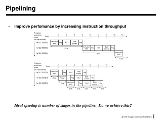
Pipelining DLX • To reduce the CPI, DLX can be implemented using a five stage pipeline. • In this example, it takes 10 cycles execute 5 instructions for a CPI of 2.
Visualizing PipeliningFigure 3.3, Page 133 Time (clock cycles) I n s t r. O r d e r
Pipelined DLX DatapathFigure 3.4 page 134 Instruction Fetch Instr. Decode Reg. Fetch Execute Addr. Calc. M U X Zero? + Write Back Memory Access 4 M U X PC ALU Regs Data Mem. M U X M U X Inst. Mem. 16 32 Sign Ext. IF/ID ID/EX EX/MEM MEM/WB • Pipeline registers are used to tranfer results from one pipeline stage to the next.
Basic Performance Issues in Pipelining • Pipelining increases the CPU instruction throughput - the number of instructions complete per unit of time - but it is not reduce the execution time of an individual instruction.
Pipeline Speedup Example • Assume the multiple cycle DLX has a 10-ns clock cycle, loads take 5 clock cycles and account for 40% of the instructions, and all other instructions take 4 clock cycles. • If pipelining the machine add 1-ns to the clock cycle, how much speedup in instruction execution rate do we get from pipelining. MC Ave Instr. Time = Clock cycle x Average CPI = 10 ns x (0.6 x 4 + 0.4 x 5) = 44 ns PL Ave Instr. Time = 10 + 1 = 11 ns Speedup = 44 / 11 = 4 • This ignores time needed to fill & empty the pipeline and delays due to hazards.
Its Not That Easy for Computers • Limits to pipelining: Hazards prevent next instruction from executing during its designated clock cycle • Structural hazards: Hardware cannot support this combination of instructions - two instructions need the same resource. • Data hazards: Instruction depends on result of prior instruction still in the pipeline • Control hazards: Pipelining of branches & other instructions that change the PC • Common solution is to stall the pipeline until the hazard is resolved, inserting one or more “bubbles” in the pipeline
Speed Up Equations for Pipelining • Stalls reduce the speedup obtained from pipelining Speedup from pipelining = Ave Instr Time unpipelined Ave Instr Time pipelined = CPIunpipelined x Clock Cycleunpipelined CPIpipelined x Clock Cyclepipelined CPIpipelined = Ideal CPI + Pipeline stall CPI = 1 + Pipeline stall CPI Speedup = CPIunpipelined Clock Cycleunpipelined 1 + Pipeline stall CPI Clock Cyclepipelined Speedup < Pipeline depth 1 + Pipeline stall CPI x
Speed Up Equation for Pipelining CPIpipelined = Ideal CPI + Pipeline stall clock cycles per instr Speedup = Ideal CPI x Pipeline depth Clock Cycleunpipelined Ideal CPI + Pipeline stall CPI Clock Cyclepipelined ASSUMING IDEAL CPI OF 1 Speedup = Pipeline depth Clock Cycleunpipelined 1 + Pipeline stall CPI Clock Cyclepipelined x x
Structure Hazards • Sometime called Resource Conflict. • Example. • Some pipelined machines have shared a single memory pipeline for a data and instruction. As a result, when an instruction contains a data memory reference, it will conflict with the instruction reference for a latter instruction.
One Memory Port/Structural HazardsFigure 3.6, Page 142 Load I n s t r. O r d e r Instr 1 Instr 2 Instr 3 Instr 4
One Memory Port/Structural HazardsFigure 3.7, Page 143 Load I n s t r. O r d e r Instr 1 Instr 2 stall Instr 3
Example: One or Two Memory Ports? • Machine A has a two port memory - access instructions and data simultaneously. • Machine B has a one port memory, but its pipelined implementation has a 1.05 times faster clock rate • Ideal CPI = 1 for both • Loads are 40% of instructions executed Ave Instr.Time A = Clock cycle A x CPI A = Clock cycle A Ave Instr.Time B = Clock cycle B x CPI B = (Clock cycle A / 1.05) x (1 + 0.4) = Clock cyle A x 1.33 Ave Instr.Time B = 1.33 Ave Instr.Time A • Machine A is 1.33 times faster
Data Hazard • Data hazard occur when pipeline changes the order of read/write accesses to operands so that the order differs from the order seen by sequentially execution instructions on an unpipelined machine
Three Generic Data Hazards InstrI followed be InstrJ • Read After Write (RAW)InstrJ tries to read operand before InstrI writes it I: ADD R1, R2, R3 IF ID EX MEM WB J: SUB R4, R1, R5 IF ID EX MEM WB
Three Generic Data Hazards Write After Write (WAW) InstrJ tries to write operand before InstrI writes it • Leaves wrong result ( InstrI not InstrJ) • Can’t happen in DLX 5 stage pipeline because: • All instructions take 5 stages, and • Writes are always in stage 5 I: LW R1, 0(R2) IF ID EX MEM1 MEM2 WB J: ADD R1, R2, R3 IF ID EX WB
Three Generic Data Hazards InstrI followed be InstrJ • Write After Read (WAR)InstrJ tries to write operand before InstrI reads it • Can’t happen in the DLX 5 stage pipeline because: • All instructions take 5 stages, • Reads are always in stage 2, and • Writes are always in stage 5 I: SW 0(R1), R2 IF ID EX MEM1 MEM2 WB J: ADD R2, R3, R4 IF ID EX WB
Compiler Scheduling for Data Hazards • Rather than just allow the pipeline to stall, the compiler could try to schedule the pipeline to avoid these stalls by arranging the code sequence to eliminate the hazard. The technique, called pipeline scheduling or instruction scheduling
Software Scheduling to Avoid Load Hazards Try producing fast code for a = b + c; d = e – f; assuming a, b, c, d ,e, and f in memory. Slow code: LW Rb,b LW Rc,c ADD Ra,Rb,Rc SW a,Ra LW Re,e LW Rf,f SUB Rd,Re,Rf SW d,Rd Fast code: LW Rb,b LW Rc,c LW Re,e ADD Ra,Rb,Rc LW Rf,f SW a,Ra SUB Rd,Re,Rf SW d,Rd
Pipelining Summary • Pipelining overlaps the execution of multiple instructions. • With an idea pipeline, the CPI is one, and the speedup is equal to the number of stages in the pipeline. • However, several factors prevent us from achieving the ideal speedup, including • Not being able to divide the pipeline evenly • The time needed to empty and flush the pipeline • Overhead needed for pipeling • Structural, data, and control harzards
Pipelining Summary • Just overlap tasks, and easy if tasks are independent • Speed Up VS. Pipeline Depth; if ideal CPI is 1, then: • Hazards limit performance on computers: • Structural: need more HW resources • Data: need forwarding, compiler scheduling • Control: discuss next time Pipeline Depth Clock Cycle Unpipelined Speedup = X Clock Cycle Pipelined 1 + Pipeline stall CPI