Source Basics
What they are and how to use them. Source Basics. Agenda. Types of sources CW Swept Signal Generator Block Diagrams Applications Specifications. Sources Generate Sine Waves. Voltage. Time. Frequency. Voltage. Spectrum Analyzer. Oscilloscope.
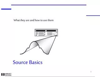

Source Basics
E N D
Presentation Transcript
What they are and how to use them Source Basics
Agenda • Types of sources • CW • Swept • Signal Generator • Block Diagrams • Applications • Specifications
Sources Generate Sine Waves Voltage Time Frequency Voltage Spectrum Analyzer Oscilloscope This is the ideal output: most specs deal with deviations from the ideal and adding modulation to a sine wave Millimeter RF Microwave 3-6 GHz 20-30 GHz 300 GHz
Types of Sources • CW • generates a single frequency, fixed sine wave • Swept • sweeps over a range of frequencies • may be phase continuous • Signal Generator • adds modulation • produces "real world" signal
Agenda • Types of sources • CW • Swept • Signal Generator • Block Diagrams • Applications • Specifications
t + t f _ cal aging CW f CW t aging t cal + _ Accuracy = 152 Hz CW Source Specifications ...Frequency . • Range: Range of frequencies covered by the source • Resolution: Smallest frequency increment. • Accuracy: How accurately can the source frequency be set. EXAMPLE Accuracy = = CW frequency = 1 GHz = aging rate = 0.152ppm/year = time since last calibrated = 1 year * * Uncertainty Voltage Frequency
CW Source Specifications ...Amplitude • Range (-136dBm to +13dBm) • Accuracy (+/- 0.5dB) • Resolution (0.02dB) • Switching Speed (25ms) • Reverse Power Protection Source protected from accidental transmission from DUT What is P out? How accurate is this number? max DUT Voltage What is P out? min Frequency
CW Source Specifications ...Spectral Purity • Phase Noise • Residual FM • Spurious CW output residual FM is the integrated phase noise over 300 Hz - 3 kHz BW harmonic spur ~30dBc phase noise non-harmonic spur ~65dBc sub-harmonics 0.5f0 f0 2f0
CW output measured as dBc/Hz Power Spectral Density -104.177 dB* Ch1 PM PSD TRACE A: frequency A Marker 10 000 Hz Y* = radrms^2/Hz -75 dB* LogMag 5 dB /div -125 dB* Start: 500 Hz Stop: 100 kHz 1k 10k 100k CW Source Specifications ... Spectral Purity: Phase Noise
CW Block Diagram Synthesizer Section • range • resolution • switching speed • spectral purity Output Section • range • level accuracy • amplitude switching speed • reverse power protection Reference Section • frequency stability • accuracy
RF CW Block Diagram Synthesizer Section Frac-N Output Section Output Attenuator ALC Modulator f Phase Detector VCO ALC Driver divide by X Reference Oscillator ALC Detector Reference Section ALC = automatic level control
divide by X TCXO OCXO Aging Rate +/- 2ppm/year +/- 0.1 ppm /year Temperature +/- 1ppm/year +/- 0.01 ppm/year Line Voltage +/- 0.5ppm/year +/- 0.001 ppm/year RF CW Block Diagram Reference Section to synthesizer section f Phase Detector Optional External Reference Input Reference Oscillator (TCXO or OCXO)
f RF CW Block Diagram Synthesizer Section ...produces accurate, clean signals N = 93.1 control Frac-N 5MHz to output section X 2 Phase Detector 931 MHz VCO multiplier 5MHz 465.6 MHz from reference section
noise frequency RF CW Block Diagram Synthesizer Section PLL / Fractional - N ...suppresses phase noise phase noise of source phase-locked-loop (PLL) bandwidth selected for optimum noise performance reference oscillator phase detector noise 20logN broadband noise floor VCO noise
Output Attenuator ALC Modulator from synthesizer section source output ALC Driver ALC Detector RF CW Block Diagram Output Section • ALC • maintains output power by adding/subtracting power as needed • Output Attenuator • mechanical or electronic • provides attentuation to achieve wide output range (e.g. -136dBm to +13dBm) ALC = automatic level control
Output Attenuator ALC Modulator ALC Driver mWave CW Block Diagram Reference Section Frac N f Phase Det VCO Sampler by X Ref Osc YIG Oscillator f Phase Detector Tuning Coils Frac-N Synthesizer Section ALC Detector f Phase Detector Output Section VCO
mWave CW Block Diagram Reference Section Frac-N 300 - 350 MHz f Phase Detector to synthesizer section VCO 30 MHz 10 MHz multiply by X f x3 Reference Oscillator Ext Ref
n = 29 then f = 8.99 GHz and f = 20 MHz LO divide by x IF mWave CW Block Diagram Synthesizer Section Sampler from reference section IF 9.01 GHz f Phase Detector Tuning Coils YIG Oscillator Frac N divide by y f Phase Detector VCO from reference section
mWave CW Block Diagram Synthesizer Section Comb Generator Sampler mixes one of the harmonics with the output of the YIG oscillator 310 MHz 8.99 GHz 27 28 29 30 31 n = 1 2 3 4 5 frequency
Applications & Critical Specifications • Local Oscillator • phase noise • frequency accuracy • Amplifier Distortion • spurious • TOI (for system) • Receiver Testing • Spurious • spurious • level accuracy
IF signal transmitter output Applications & Critical Specifications As a Local Oscillator DUT poor phase noise spreads energy into adjacent channels poor frequency accuracy will cause transmitter to be at the wrong frequency
f1 DUT output RF f2 isolator f1 f2 test system third order products will also fall here amplitude spurious signals from source can corrupt measurement fL = 2f1 - f2 fU = 2f2 - f1 frequency Applications & Critical Specifications Amplifier Testing Intermodulation Distortion
in-channel signal (modulated signal) IF signal out-of-channel signal (CW or modulated signal) DUT source output IF Rejection Curve spur from source and/or high levels of phase noise can cause a good receiver to fail Level (dBm) Frequency Applications & Critical Specifications Receiver Testing Spurious Immunity
Agenda • Types of sources • CW • Swept • Signal Generator • Block Diagrams • Applications • Specifications
Sweeper Specifications ...Frequency • ramp sweep • accuracy • sweep time • resolution f2 frequency f1 t2 t1 time • step sweep • accuracy • number of points • switching time f4 f3 frequency f2 f1 t1 t2 t3 t4
level accuracy spec power flatness spec f1 f2 frequency } P2 power sweep range power P1 Sweeper Specifications ...Amplitude Frequency Sweep • Level Accuracy • Flatness Source Match (SWR) Power Sweep • Power Sweep Range Power Slope Range • Source Match (SWR)
from reference section Sampler 9.01 GHz divide by x f YIG Oscillator Phase Detector Tuning Coils S/H divide by y DAC Sweeper Block Diagram Frequency Sweep: Open Loop • Phase continuous • PLL open • Synthesize start frequencies • Tuning characteristics must be precisely known mWave Source: Synthesizer Section
Frac-N f Phase Detector VCO Sweeper Block Diagram Frequency Sweep: Closed Loop • Fully synthesized sweep • Phase continuous within • PLL never loses lock • Limited frequency range RF Source: Synthesizer Section
Output Attenuator ALC Modulator from synthesizer section source output ALC Driver ALC Detector Sweeper Block Diagram Power Sweep • Drive ALC Modulator • Level accuracy maintained • Broad sweeps may require switching output attentuator Output Section
Applications & Critical Specifications • Frequency Response • Frequency Accuracy • Output Power (Level) Accuracy • Flatness • Speed • residual FM • Amplifier Compression • Power Range
Applications & Critical Specifications Frequency Response Testing Sweeper Input • Frequency Accuracy • Output Power (Level) Accuracy • Flatness • Speed • residual FM LO
Log Mag 5.0 dB/ Ref -15.00 dB 1:Transmission BW: 429.600 MHz CF: 2405.782 MHz 5 dB Q: 5.60 Loss: -0.84 dB 1 0 -5 3 5 6 -10 Ch1 -20 -25 -30 1 -35 Abs Center 2 450.212 MHz Span 1 099.577 MHz Applications & Critical Specifications Frequency Response Testing Who Cares About Accuracy?
1 dB compression point Power Out Power In Applications & Critical Specifications Amplifier Compression • Power Range The 1 dB compression point is a common amplifier specification used to identify the linear operating range of an amplifier. Power sweep is available on some HP sources.
Agenda • Types of sources • CW • Swept • Signal Generator • Block Diagrams • Applications • Specifications
Signal Generators • Calibrated, variable frequency over a broad range • Calibrated, variable ouput level over a wide dynamic range • Calibrated modulation • Analog (AM, FM, PM, Pulse) • Digital (IQ) • Format Specific
Modulation ...Where the information resides p f V= V(t) sin[2 f(t) + (t)] AM, Pulse PM FM q V= V(t) sin[ (t)]
Modulation: Analog Amplitude Modulation Carrier Important Signal Generator Specs for Amplitude Modulation Voltage Time • Modulation frequency • Linear AM • Log AM • Depth of modulation (Mod Index) Modulation
p V= V(t) sin[2 f t + m(t)] b c F /F Important Signal Generator Specs for Frequency Modulation b = D dev mod Voltage Time Modulation: Analog Frequency Modulation • Frequency Deviation • Modulation Frequency • dcFM • Accuracy • Resolution
p V= V(t) sin[2 f t + m(t)] b c Important Signal Generator Specs for Phase Modulation • Phase deviation • Rates • Accuracy • Resolution Voltage Time Modulation: Analog Phase Modulation b = Df peak
p V= V(t) sin[2 f t + m(t)] b c b = Df peak F /F b = D dev mod Modulation: Analog PM is Really the Same as FM... FM Modulator PM Modulator
Modulation: Analog Voltages of FM/PM Frequency Components Bessel Functions of the First Kind 1 J0 0.8 J1 0.6 J2 J3 0.4 J4 0.2 J5 0 J6 -0.2 J7 -0.4 J8 J9 -0.6 0.0 2.0 4.0 6.0 8.0 9.9 J10 b 5.52
Important Signal Generator Specs for Pulse Modulation • Pulse width • Pulse period • On/Off ratio • Rise time Modulation: Analog Pulse Modulation T Rate=1/T Rise time On/Off ratio Power t Time Pulse Width 1/T 1/t Power
f Signal Generator Block Diagram FM and PM control Frac-N to output section X 2 Phase Detector VCO multiplier d/dt divide by X function generator from reference section external FM/PM input
Signal Generator Block Diagram AM and Pulse ALC Modulator Burst Modulator Output Attenuator from synthesizer section source output Burst Mod Driver ALC Driver function generator ALC Detector Ext AM ALC Hold Ext Pulse
Digital Modulation ...signal characteristics to modify Amplitude Frequency Phase Both Amplitude and Phase
f p V= V(t) sin[2 ft + ] Digital Modulation ...Amplitude Shift Keying (ASK) V(t) = RF waveform V =
p f V= Vo sin[2 ft + (t)] f 1 f 2 Digital Modulation ...Phase Shift Keying (BPSK) f (t) =
p f V= Vo sin[2 ft + (t)] f p 1 = 3 /4 f (t) = f p 2 = /4 f p 3 = - /4 f p 4 = - 3 /4 Digital Modulation ...Phase Shift Keying (QPSK)
f Digital Modulation PSK Implementation: PLL Method Frac-N Phase Detector VCO f(t) d/dt Reference Oscillator external modulation input
p f V= Vo sin[2 ft + (t)] p f = Vo cos[ (t)] sin[2 ft] + p p f Vo sin[ (t)] sin[2 ft + /2] f p 1 = 3 /4 f (t) = f p 2 = /4 f p 3 = - /4 f p 4 = - 3 /4 Digital Modulation PSK Implementation: IQ Method