Download
1 / 29
290 likes | 407 Vues
Learn about the mission, state-of-the-art, and technology development for high gradient acceleration in normal conducting accelerators. Discover methods to understand physical mechanisms and overcome limitations. Understand the key studies and collaborative efforts between the US and Japan.

E N D
Study of High Gradient Acceleration in Normal Conducting Accelerator US-Japan workshop Dec. 20, 2011 Toshi Higo (KEK)
Contents • Mission of the study • State of the art • What prevents us from high gradient • Trial to understand physical mechanism • How to develop the technology • Contribution based on US-Japan program US/Japan Workshop (Toshi Higo)
Toward higher energyGradient in normal conducting accelerator • Low energy application • 100kW, a few MV/m, 1MV • Medium energy application • 1MW, 10MV/m, 10MV • Established big accelerator • a few 10MW, 20MV/m, 1GeV • On-going high energy machine • 40MW, 40MV/m, 10GeV • Very high energy machin • 50MW, 100MV/m, 100GeV US/Japan Workshop (Toshi Higo)
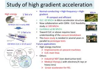
Target gradient for LC and required stability • 1990’s at 100MV/m, 20cm • “gradient established” in short section • No care on BDR etc. • 2000’s at ~50MV/m, 60cm • HOM managed • Damage observed but BDR meets req. • 2010’s at 100MV/m, 25cm • Targeting the regime 100MV/m • Stability: 1BD/structure/3days US/Japan Workshop (Toshi Higo)
Mission of high gradient study • Understand vacuum discharge mechanism • Trigger mechanism • Evolution to discharge over big volume • Damage mechanism • Search for suppression technology • Material, geometry, processing method, ….. • Serve for • Stable acceleration for present machines • High energy accelerator such as LC US/Japan Workshop (Toshi Higo)
State of the art for LC in undamped Speculated from higher gradient data BDR decreases continuously over a few thousand hours. It meets the requirement of a linear collider, CLIC. US/Japan Workshop (Toshi Higo)
State of the art for LC in damped More BDR in damped than undamped, but BDR decreases as time. We are on the edge? Need to understand and confirm! US/Japan Workshop (Toshi Higo)
Difference of #BD until reaching goalBD can be needed or avoided? Undamped Damped More BD’s are required for damped!? Why? Can it be reduced? BD’s are essentially needed? Higo Nextef meeting on 111020
Field emission seems related to high gradient TD18_Disk worst T18_Disk TD24_Disk T24_Disk best (51ns processing) Eacc for peak dark current of 10 m 90MV/m 70MV/m 100MV/m (80MV/m) Need to understand the relation between the two. US/Japan Workshop (Toshi Higo)
Discharge pits around iris + Crystal pattern by pulse surface heating. US/Japan Workshop (Toshi Higo) Photo John Van Pelt
Faya Wang Breakdown rate vspulse heating TD18 BDR Damped DT~ Hs2 Undamped DT BDR closely correlates to pulse temperature rise US/Japan Workshop (Toshi Higo)
V. Dolgashev, AAS 2010 Importance of magnetic field Surface electric field Magnetic field Pulse surface heating Accelerator gradient Peak pulse heating plays an important role, rather than geometry. US/Japan Workshop (Toshi Higo)
Undampeddamped Hs US/Japan Workshop (Toshi Higo)
Breakdown trigger comes from high magnetic field area? Strange shape appears at highest Hs point. Pulse heat damage • Surface current is large! • 400kA/m over 0.5mm thick • 1A/mm2 • >> IC problem • (~0.1A/mm2) Hs max High current Markus Aicheler 13. Oct. 2010 US/Japan Workshop (Toshi Higo)
Electromigration? Taken from web: University of Cambridge. Direct electric field a=screening factor Diffusion process Fd = aZeE Q=Activation energy Conduction electron wind D = D0exp (–Q/RT) s=collision cross section l=mean free path Crystal defect, boundary, void, etc. are related Fw = –eneλσiE US/Japan Workshop (Toshi Higo)
What limits high gradient is: Arc, Discharge, Breakdown, …. In vacuum • Appears in such as • Processing • Period needed until reaching goal • How many BD’s are needed to reach goal • Breakdown • Luminosity loss, material damage • Requirement of spare units recovery time • Damage • Cumulative damage perturbs frequency US/Japan Workshop (Toshi Higo)
We need to understand physical mechanism of vacuum arc • Possible and proposed mechanisms • Sharp edge Es enhancement FE • Es Maxwell’s stress pull up crystal FE plasma development • Hs pulse heating fatigue edges and ruptures high Es • Hs high current density electromigration • BD Trigger and evolution to discharge • Understand mechanism • Estimate degree of damage US/Japan Workshop (Toshi Higo)
How to study mechanism and develop suppression technology • Prototype test • GLC/NLC CLIC • Study with simple geometry • Single-cell setup, waveguide, DC, etc. • Developments in the area such as • Geometry, fabrication, assembly technique • Processing method US/Japan Workshop (Toshi Higo)
Keys studies supported by US-Japan • KEK • Parts fabrication • Long-term high gradient test • SLAC • Chemical polishing and assembly • Hydrogen furnace and vacuum baking • Very high power test • Various specific tests • US high gradient collaboration • Exchange of ideas and experimental results • Specific tests in special conditions and environments US/Japan Workshop (Toshi Higo)
SLAC/KEK prototype test flow Design for CLIC (CERN) High power test (NLCTA-SLAC) High power test (Nextef-KEK) Fabrication of parts (KEK) CP (SLAC) VAC bake (SLAC) Bonding (SLAC) US/Japan Workshop (Toshi Higo)
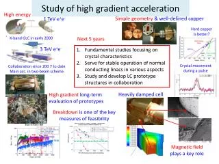
What to be studied toward future • Explore basic studies (KEK and SLAC) • Continue evaluation of prototype structures (KEK and SLAC) • Understand structure whole life and improve processing (KEK) • Initial ramp up stage • Establish target operation • Stability through long-term operation • Study feasibility of much higher gradient (SLAC) • SW approach and material approach • To understand practical operation regime US/Japan Workshop (Toshi Higo)
Pulse heating and surface deterioration (done) Hard material is better. SLAC: L. Laurent Hardness Test Value Y.Higashi, Joint MAP & High Gradient RF collaboration Workshop, 1-4 November, 2011,
Scanning field emission microscope PIEZO actuator Capacitance gauge W-Tip W-Tip Sample XY stage Field emission and surface of crystal characteristics. US/Japan Workshop (Toshi Higo)
Study with single-cell setup Clean setup High field at center cell Test setup at SLAC US/Japan Workshop (Toshi Higo)
Study damped cell Iris can be Cu, Mo, SS Test setup being prepared at KEK
Thinking of possible trailsDiffusion bonding BrazingClamped ? Downstream side Diffusion-bonded surface may be improved by brazed smooth surface No further enhancement of current Upstream side Milled surface Crystal defects OK? Revisit quadrant? divide along current path No current interruption 1mm 1mm US/Japan Workshop (Toshi Higo)
Other on-going basic tests In-situ inspection Clad (Cu/SS, Cu/Mo) Large grain material Crystal characteristics Cu and Nb in cold setup US/Japan Workshop (Toshi Higo)
Toward much higher gradient Cu/Moly clamp by KEK SW study at SLAC US/Japan Workshop (Toshi Higo)
Conclusion • Basic studies and prototype evaluations are performed in cooperative manner between US and Japan. • It offers essential understanding for the high gradient realization based on copper. • Magnetic field and associated high current on a crystal structure play an important role. • Trigger mechanism of breakdown should be understood through studies with simple setups. • US pursuits real high gradient while Japan evaluates up to 100 MV/m. These studies are complementally and offer a baseline idea for linear collider application. US/Japan Workshop (Toshi Higo)