Download
1 / 42
450 likes | 598 Vues
TX Mask Shoulders vis-à-vis ACI. Authors:. Date: 2011-05-04. Abstract. A comment requesting a change to the way spectral mask levels are calculated was submitted [1]

E N D
TX Mask Shoulders vis-à-vis ACI Authors: Date: 2011-05-04 Matt Fischer, Broadcom
Abstract • A comment requesting a change to the way spectral mask levels are calculated was submitted [1] • The comment states that due to the increase in 11ac in the allowable in-band ripple from +/-2dB to +/-4dB there is a risk that the adjacent channel leakage (which is measured relative to peak power) will also increase by 2dB if device manufacturers take advantage of the increased allowable in-band ripple and hence will increase interference and reduce network Tput • We therefore study here the effect on system Tput of increased adjacent channel leakage by 2dB to quantify the potential degradation • We use PHY system simulations to compare the effect of different CCA levels on system Tput as in [2] • We also show results of some MAC-level system simulations Matt Fischer, Broadcom
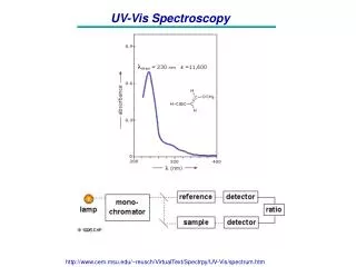
Spectral Mask Matt Fischer, Broadcom
PHY System Simulation Parameters • 36 APs and 4 STA per AP are dropped in an area of size 300x300 ft and 600x600ft • APs are placed regularly with 5ft std • STAs are associated with closest AP according to path loss (which includes random shadowing) • One valid transmission per BSS is assumed • BSSs are chosen randomly that meet CCA rules (50% probability to choose an AP as transmitter) • After all transmitters were chosen SINR is calculated at each receiver and mapped to MCS • SISO links over one 40MHz channel are assumed with 15dBm transmit power • CCA level is fixed at -79dBm • 4 different frequencies are assigned to the 36 AP in two different ways: • Ordered frequency allocation • 2 4 2 4 2 4 • 1 3 1 3 1 3 • 4 2 4 2 4 2 • 3 1 3 1 3 1 • 2 4 2 4 2 4 • 1 3 1 3 1 3 • Random frequency allocation – in each drop each BSS randomly chooses one of four frequencies • Simulation uses 50 drops and 250 TXOP per drop. In each TXOP a maximum number of transmitters across all frequencies are chosen without violating the CCA levels • The Baseline ACL was assumed either -25dBr or -40dBr for all other three frequencies to separately reflect the average interference values with adjacent and alternate adjacent ACL. • Tput loss is then measured with -23dBr and -38dBr Matt Fischer, Broadcom
Results Matt Fischer, Broadcom
MAC Sim Parameters Case 5 • Case 5: • Office environment • Approx 30 x 50 m • One floor simulated • 2 BSS • 1 BSS on each of two adjacent channels • AP0 + 10 clients • AP11 + 10 clients • TCP flows in both directions for every AP-client pair • ED-CCA level = -62 dBm • CRS level = -90 dBm Matt Fischer, Broadcom
MAC Sim Topography Case 5 Matt Fischer, Broadcom
MAC Sim RXPWR Case 5 Matt Fischer, Broadcom
MAC_SIM Results Case 5 • s_425_A23_5G_B_20_2x2_R_e10_c62 = 82.29 Mbps • s_425_A25_5G_B_20_2x2_R_e10_c62 = 83.44 Mbps • s_425_A38_5G_B_20_2x2_R_e10_c62 = 84.61 Mbps • s_425_A40_5G_B_20_2x2_R_e10_c62 = 84.67 Mbps • s_425_A99_5G_B_20_2x2_R_e10_c62 = 92.30 Mbps Matt Fischer, Broadcom
MAC Sim Parameters Case 6 • Case 6: • Same floor area as Case 1 • 2 BSS • 1 BSS on one channel, 1 BSS on a second channel (adjacent) • 2 clients per BSS • 6 STA total AP plus clients • TCP flows in both directions for every AP-client pair • ED-CCA level = varied from -53 dBm to -71 dBm • CRS level = -90 dBm Matt Fischer, Broadcom
MAC Sim Topography Case 6 Matt Fischer, Broadcom
MAC Sim RXPWR Case 6 Matt Fischer, Broadcom
MAC_SIM Results Case 6 Matt Fischer, Broadcom
MAC Sim Parameters Case 7 • Case 7: • Same floor area as Case 1 • 2 BSS • 1 BSS on one channel, 1 BSS on a second channel (adjacent) • 2 clients per BSS • 6 STA total AP plus clients • Note client placement • Flows: • U = 4x TCP flows only UPLINK for each AP-client pair • D = 4x TCP flows only DOWNLINK for each AP-client pair • UD = 2x TCP flows: AP0 -> C2, C4 -> AP3 • DU = 4x TCP flows: AP0 -> C2, C1 -> AP0, C4 -> AP3, AP3 -> C5 Matt Fischer, Broadcom
MAC Sim Topography Case 7 Matt Fischer, Broadcom
MAC Sim RXPWR Case 7 Matt Fischer, Broadcom
MAC_SIM Results Case 7 Matt Fischer, Broadcom
MAC Sim Parameters Case 8 • Case 8: • Slightly different from case 7 – APs are farther apart • Attempt to get main link margin to be smaller • 2 BSS • 1 BSS on one channel, 1 BSS on a second channel (adjacent) • 2 clients per BSS • 2 AP and 4 clients (effectively only two clients) • 2 TCP flows: • U = C4 -> AP3, C2 -> AP0 • D = C4 <- AP3, C2 <- AP0 • UD =C4 -> AP3, AP0 -> C2 Matt Fischer, Broadcom
MAC Sim Topography Case 8 Matt Fischer, Broadcom
MAC Sim RXPWR Case 8 Matt Fischer, Broadcom
MAC_SIM Results Case 8 Matt Fischer, Broadcom
MAC Sim Parameters Case 9-C2R4 • Case 9-C2R4: • 3 Floor office building • 9 BSS per floor (2500 sq ft per BSS maximum) • Semi-rigid AP locations with random variance • Random channel assignment from 2 adjacent channels • 1-3 clients per BSS (randomly assigned, randomly located) • Over 110% of BSS area • TCP flows: • 3:1 ratio DOWN to UP, randomly assigned • One flow per client • CCA level = -62 dBm • R4, R5, R6 = distinct randomizations Matt Fischer, Broadcom
MAC Sim Topography Case 9-C2R4common color = common channel Matt Fischer, Broadcom
MAC Sim Topography Case 9-C2R4common color = common channel Matt Fischer, Broadcom
MAC Sim RXPWR Case 9-C2R4 Matt Fischer, Broadcom
MAC Sim Topography Case 9-C2R5 Matt Fischer, Broadcom
MAC Sim RXPWR Case 9-C2R5 Matt Fischer, Broadcom
MAC Sim Topography Case 9-C2R6 Matt Fischer, Broadcom
MAC Sim RXPWR Case 9-C2R6 Matt Fischer, Broadcom
MAC Sim Topography Case 9-C3R73 Channels to choose from Matt Fischer, Broadcom
MAC Sim RXPWR Case 9-C3R7 Matt Fischer, Broadcom
MAC Sim Topography Case 9-C4R8Four channels to choose from Matt Fischer, Broadcom
MAC Sim RXPWR Case 9-C4R8 Matt Fischer, Broadcom
MAC Sim Results Case 9 Matt Fischer, Broadcom
MAC Sim Parameters Case 10 • Case 10: • 1 floor • 2 BSS • Semi-rigid AP locations with random variance • 2 adjacent channels • Varying TX Mask shoulders • Randomized placements • Randomized up and down pair flows • 3:1 ratio DOWN to UP, randomly assigned • One flow per client Matt Fischer, Broadcom
MAC Sim Topography Case 10-0 Matt Fischer, Broadcom
MAC Sim Topography Case 10-16 Matt Fischer, Broadcom
MAC Sim Topography Case 10-17 Matt Fischer, Broadcom
MAC Sim Results Case 1020 randomized cases Matt Fischer, Broadcom
MAC Sim Results Case 1020 randomized cases averaged Matt Fischer, Broadcom
Simulation Conclusions • Minimal per-link Tput degradation. • No sum network Tput degradation for increase from -40 to -38dBr • Small (few % points) network Tput degradation for increase from -25 to -23dBr probably due to reduced average number of concurrent transmissions • Notes: • In reality when many channels are available (as in the case of 40MHz channels) the interference level will be mostly -40dBr since most channels are not adjacent. • Interference level of -25dBr will only be the dominant case if only 2-3 channels are available • The simulation assumes full buffer – all nodes always have something to transmit – this is a worst case scenario from interference point of view. • While it’s not clear that implementations of 802.11ac will actually have in-band signal power variations of +/-4dB, the effect on network Tput is modest. Therefore, we propose not to include restrictions (equations, etc.) to the spectral flatness. Matt Fischer, Broadcom
References [1] 11-11-0276-11-00ac-tgac-d0-1-comments.xls • CID 488 [2] 11-11-0061-00-00ac-cca-threshold-levels.ppt Matt Fischer, Broadcom