LCLS Event System
This document outlines the engineering perspectives on the data transfer mechanics from Event Generator (EVG) to Event Receiver (EVR) as it pertains to the LCLS system. It emphasizes the complexity of beam-synchronous acquisition and control, detailing timing requirements, trigger sequences, and the management of all associated hardware components. The document further highlights existing and future issues, status updates, and critical tasks that need addressing to ensure optimal system functionality during commissioning, including algorithms for pulse-by-pulse control and data acquisition strategies.


LCLS Event System
E N D
Presentation Transcript
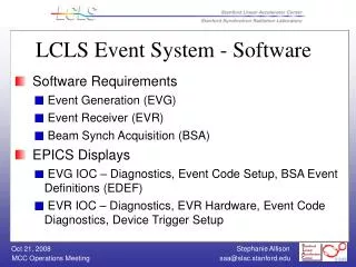
LCLS Event System • Outline • HW Block Diagram • Timing Requirements • Time Lines • EVG to EVR Data Transfer • Beam-Synchronous Acquisition and Control • Issues/Comments • Status/To-Do
Modulator Triggers HW Block Diagram Beam Rate, Beam Path Trigger Delays and Pulse Widths, Event Codes per Output Channel Existing Control System PNET Channel Access Trigger EVG Fan Out Master EVG P N E T IOC EVR A D C BPM IOCs EVG Fan Out EVR LLRF IOCs 360Hz Fiducial Timing Pattern, Timestamp, Event Codes Trigger RF Timing 119MHz RF Clock P/A Acq & Cntrl Beam Rate, Beam Path EVR Camera IOCs Down stream EVG IOC EVG Fan Out Future MPS Trigger To Downstream EVRs Camera
Event Time Line – 120 Hz Beam 360Hz Fiducial F0 F1 F2 F3 F4 F5 F6 F7 Time (msec) 0 2.8 5.6 8.3 11.1 13.9 16.7 19.4 Beam B0 B1 B2 Kly Standby S0 S1 S2 CX2 BPM Calib CX0 CY0 CX1 CY1 Timing data for next Beam pulse T1 T1a T1b T2 T2a T2b T3
Event Time Line – 1 Beam Pulse (B1) Record processing (event, intr) Post-Beam Acq B1 Timing Data in records, waiting to be used Acq – BPM, Toriod, PMT, Camera Beam B2 Timing Data Received Kly Standby Laser Control Fiducial F3 T2 B1 S1 Time (msec) 1 1-b 1-a 0 1+c 1+d 1+e
Event Applications • Beam-Synchronous Control: rules and algorithm for creating EVG trigger sequences on a pulse-to-pulse basis • Algorithm change on-the-fly based on user requests • Single-Shot vs continuous beam pulses – enforce minimum delay between single-shot requests • Bunch length measurement • Rate limit • Beam destination • MPS rate limit and destination requests • Send out calibration, standby, and software triggers during non-beam time slots
Event Applications (cont) • Beam-Synchronous Acquisition: mechanism for users to request pulse-by-pulse acquisition across multiple IOCs: • Single-shot or multiple contiguous pulses • Include or exclude a pulse from resultant waveforms based on information in the timing pattern for that pulse • Can be implemented by either data mining of large data/timing-pattern arrays • …or use the timing system to trigger data copy to special records based on preset conditions, requires reserve/release of special records
Immediate Issues/Comments • EVG RF input divider – new circuit added to EVG • Do we need EVR with RF recovery (EVR with clock)? 119Mhz availability throughtout? • Fiber plant: • Match network bulk cable where possible • Where is single mode fiber needed? Between fanouts? To EVR w/RF recovery? • How much EVR daisy-chaining can we do? • Daisy chain vs tap to split • No plans for redundancy • TTL triggers – long trigger cables need design • Not enough testing has been done • Schedule…….
Future Issues • Modulator triggers on existing control system – how to rate-limit from new system • Handling non-LCLS beams – add more beam-pulse-dependent info (ie, bunch charge) to timing pattern for IOC apps • How to upgrade PMC-EVR firmware
Status (Dayle Kotturi) • Received the EVG/EVR 200 series VME hardware (which sends up to 2K data buffer) • Received the EVR 200 series PMC module • Adapted driver and device support to: • send the PNET data buffer (measured 66 µs transfer) • be OSI (running on mvme6100, RTEMS4.7) • with help from Till Straumann, Eric Bjorklund, Timo Korhonen, Jukka Pietarinen and Bob Dalesio
Status (cont) • Stephanie Allison and Mark Crane coming up to speed • Test stands for HW folks not yet ready • Rack/cable design for injector/BC1 well underway • Procurement underway
To-Do • Finish PMC-EVR driver and test (share PMC-EVR and VME-EVR driver as much as possible) • EVG sequence RAM programming at 360 Hz • EVG rules and algorithm definition for Jan commissioning • Add support for EVR timing pattern data records (in place well before next beam pulse) • Jitter testing • Interface with other subsystems needs review • Commissioning test plan